


Magazine Archive
Home -> Magazines -> Issues -> Articles in this issue -> View
Electro-Music Engineer (Part 1) | |
Tuning Up — A Review of VCO Calibration MethodsArticle from Electronics & Music Maker, November 1982 | |

There are several synthesiser kits available in the UK and the use of modern techniques in some make them a cost-effective choice for those with the ability to construct their own equipment. What seems to deter most would-be constructors, however, is the 'difficulty' of calibrating the voltage controlled oscillators (VCO's). The word 'difficulty' is in inverted commas because it is used by many potential constructors and not by the writer who in recent years has discussed the subject with many constructors and has usually provided them with a technique which suits their available resources.
Some potential constructors may have taken the trouble to read construction notes relating to calibration and usually end up being more confused. This is not because the instructions are unclear but simply, of necessity, they refer to 'R this' and 'RV that' and the whole thing becomes gibberish unless one is actually undertaking the calibration. To remedy this situation we review the main techniques available for calibration of VCO's so that constructors may more clearly assess which method suits the equipment available to them. In a later issue there will be a project which should fulfill most requirements for calibrating and keeping the synthesiser in tune.
The emphasis of the article is on calibrating exponential voltage controlled oscillators, that is, oscillators in which a unit change to input voltage will alter frequency in relationship to the equally tempered scale. Usually this scale is a one volt change of input voltage to alter frequency by one octave; as used in the E&MM 'Spectrum' and many other synthesisers. The methods may, however, be readily applied to other scales and also to linear oscillators in which the keyboard controller derives the exponential voltage required for the equally tempered scale.
For those wishing to relate the methods to a practical situation reference is made to the 'Spectrum' synthesiser and the appropriate circuits will be found in the January and February issues of E&MM.
Accuracy and stability
We referred earlier to cost-effective kits. A major part of their effectiveness is the ability to calibrate them to an accuracy which is suitable for musical application. There are some kits available which frankly are only suitable for making funny noises. One supplier mentions that if the scaling is not better than a quarter of a semitone then there may be something wrong with the oscillator. In other instances the frequency drift is so bad as to make nonsense of calibrating. We will assume, however, that the VCO being calibrated is of good design and capable of attaining the required accuracy and stability.
Irrespective of the exact design the constructor should be aware of the several factors which affect the accuracy and stability of even the best VCO. The most important are:
a) Supply Voltage. Invariably within the VCO design a reference current is established, for example, in the 'Spectrum (E&MM January '82, P.90, Figure 9) resistors R175 and R176 set up a reference current of 10uA from the +15V supply into pin 13 of the CEM 3340 VCO, IC 15. At a frequency of about 1kHz a variation of 100mV into these resistors will cause a change of about 7Hz. Clearly the stable power supply used is essential. Other voltage controlled oscillators may be more sensitive to supply variations and in some instances the negative supply voltage will be the most critical. Thus before carrying out the calibration ensure that the power supplies are set as accurately as possible to their rated output voltage. Normally a drift in supply voltage will only affect tuning which can be counteracted by the 'fine tuning' control found on most VCO's. If, however, abnormal frequency drifting is encountered with a VCO which is known to be reliable then the first step is to check the stability of the power supply. Also beware of tagging on other equipment to the synthesiser's power supplies. In some instances this may cause instability as its current limit is approached. In particular, avoid connecting equipment with high current surges, such as LED's and some low frequency oscillators since their intermittent drain on power may cause unwanted modulation effects.
b) Control Voltage. This will normally be derived from the keyboard controller. Again at about 1kHz a variation of only 10mV will alter frequency by about 7Hz. This 10mV will often be the limit of measurement with a three and a half digit voltmeter so if an external control voltage is used for calibration (see later) then one should be aware of the accuracy required. When the calibrating voltage is derived from a calibrated keyboard then usually the required accuracy is available. The output voltage must remain constant during the period of the calibrating step and this should always be checked.
Relating to the above is that all other variable voltage sources connected to the VCO should normally be disconnected during calibration. Even the fine tuning control may become disturbed during calibration and if possible it should be disconnected.
c) Timing Capacitor. The timing capacitor for IC15, mentioned above in the 'Spectrum', is C31. Although a temperature stable, low leakage capacitor is used there remains the possibility of leakage due to dirt and flux on the foil side of the PCB. The charging currents in modern VCO's are of low level, for example, below 100Hz the currents may be less than one microampere.
Additionally at high frequencies flux becomes more conductive. It is therefore desirable to clean the foil side of the PCB, at least in the area of the timing capacitor, using either a proprietary solvent or by careful scraping.
d) Temperature. The CEM 3340 VCO IC has excellent temperature stability due to its unique compensating technique. The method compensates for variations in the temperature of the chip within the integrated circuit package and also for changes in ambient conditions which in turn will influence the temperature of the IC. In other designs external temperature compensating resistors may be used. While the package protects the CEM 3340 from rapid fluctuations in temperature, such as those occurring from draughts, other designs are more susceptible to such variations. Furthermore, some of the components external to the VCO may be more temperature sensitive than the IC. Before commencing calibration allow sufficient time for temperature equilibrium to be reached and protect the VCO from rapid variations in temperature.
The Calibrating Voltage
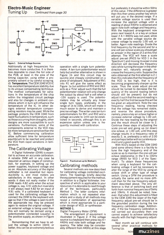
A Digital Voltmeter (DVM) is essential to achieve an accurate calibration. A reliable DVM will in any case be required at various stages of construction, for example, in setting up the power supplies, keyboard voltage and so on. Absolute accuracy of the digital voltmeter is not essential but reproducibility is, and most meters are satisfactory in this respect. In other words it does not really matter if the DVM reads 4.82 volts when the actual voltage is, say, 4.91 volts but invariably it will always read 4.82 for an input of 4.91 volts. If a calibrated keyboard is used for the calibrating voltage then connect the DVM to the keyboard voltage so that if the voltage is seen to drift the appropriate key may be pressed again to restore the original voltage. If an external voltage is being used then this will normally be derived using a potentiometer connected (usually) to the positive supply, as shown in Figure 1a.

Figure 1. External Voltage Sources.
Remembering that we have to adjust the voltage to within 10mV, or better, this can be an extremely tedious operation with a single turn potentiometer. A ten-turn potentiometer would help but another alternative is shown in Figure 1b and this circuit may be quickly and cheaply constructed on a piece of stripboard. Adjustment of RV1 into R1 will give the same effect as Figure 1a but addition of RV2 and 3M3 acts as a 'Fine' adjust such that the full potentiometer rotation will only change the output by about half a volt when a -15V supply is used. The potentiometers may be virtually any linear single turn types, preferably in the range of 1k to 100k, which will make it much easier to derive and maintain a precise voltage. The writer uses ten turn potentiometers for RV1 and RV2 and a voltage accurate to 1mV can be established in seconds, although this is an expensive option unless one is frequently involved with calibration.
Calibrating methods
Several methods are now described for calibrating voltage controlled oscillators. The headings briefly describe the equipment required for the method, in addition to a Digital Voltmeter. Irrespective of which is applicable to your resources it is desirable to read through all of the techniques, particularly Method 1. The latter contains information which is not repeated elsewhere and a study of all methods may reveal a combination of approaches which is more appropriate to a particular design of VCO, or synthesiser.
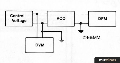
Figure 2. Practical set-up for Method 1.
METHOD 1. Digital Frequency Meter (DFM)
The arrangement of equipment is illustrated in Figure 2. If the voltage source is a keyboard then press key A = 440Hz and note both voltage and frequency. The latter may be considerably different from 440Hz at this stage but preferably it should be within 50Hz of this value. If the difference is greater than this then press another key which will put you in the desired range. If a variable voltage source is used then increase the applied voltage until a reading of about 440Hz is obtained and again note both voltage and frequency. With the keyboard arrangement now press next lowest A, or a key an octave lower if A = 440Hz was not used, while with the variable voltage source decrease voltage by exactly 1.00 volt, or better. Again note readings. Divide the first frequency by the second and for a one volt per octave scale you should get an answer in the region of 2 at this first attempt. The VCO will have a scale adjust pre-set (RV23 for VCO 1 in the 'Spectrum') and moving its wiper in one direction will decrease the frequency ratio while turning the wiper in the other direction will, naturally enough, increase the frequency ratio. Suppose the ratio obtained at the first attempt is 2.1 then this indicates that the frequency of the VCO is too high, that is it is becoming progressively sharper up the scale. Thus the scale adjust pre-set should be turned to decrease the frequency of the second reading (which should still be present) but do not adjust it such that the second reading is exactly half the first because this will be too great an adjustment. Note the new frequency reading, having checked that the voltage has remained stable, and reverse the above procedure, namely, press a key an octave higher or increase external voltage by 1.00 volt. Divide the new reading by the original and the result should be closer to 2. Continue these steps of adjusting the scale pre-set and going up (or down) one octave, or 1.00 volt, until this step change results in a frequency ratio of exactly 2, ie, preferably a ratio of 2.00 and perhaps better with accurate equipment and a good quality VCO.
With VCO's based on the CEM 3340 (and some others) there is a facility to tune the high frequency end of the scale so as to maintain the one volt per octave relationship in the 5 to 10kHz range (RV55 for VCO 1 of the 'Spectrum'). To obtain these frequencies when using a keyboard for the calibrating voltage it will be necessary to alter the range of the VCO by using an octave shift or other type of range switch. Using a DFM the procedure is virtually the same and no more difficult than for the low frequency adjustment described above. The only difference is that of switching back and forth from nominal frequencies of 5kHz and 10kHz. It should be noted, however, that when this adjustment is fitted to the CEM 3340 the wiper of the high frequency adjust pre-set should be in the grounded position during the low frequency calibration stage. Additionally, if the low frequency calibration is not carried out accurately then one cannot expect to achieve satisfactory results with the high frequency adjustment.
Next month we will continue with several other practical methods for Tuning Up.
Series - "Tuning Up"
Read the next part in this series:

Electro-Music Engineer (Part 2)
(EMM Jan 83)
All parts in this series:
Part 1 (Viewing) | Part 2
More from these topics
 Modular Effects Rack Project (Part 1) |
 ICs for Electro-Music (Part 1) |
 Workbench - Signal Processors — the saga continues |
 Gnome Instrument Interface - Using the 2720-11 Envelope Follower |
 Studio Sound Techniques (Part 1) |
 Speaker Drive Units - Control Room (Part 1) |
 Workbench - Remote Control System |
 Test Tone Oscillator |
 Workbench - CHECKA |
 XLR Connectors Sounded Out |
 Short Circuit - Time Machine Revisited |
 First Guitar Faults - Your First Guitar |
Browse by Topic:
Electronics / Build
Maintenance / Repair / Modification
Publisher: Electronics & Music Maker - Music Maker Publications (UK), Future Publishing.
The current copyright owner/s of this content may differ from the originally published copyright notice.
More details on copyright ownership...

Electronics & Music Maker - Nov 1982
Topic:
Electronics / Build
Maintenance / Repair / Modification
Series:
Tuning Up
Part 1 (Viewing) | Part 2
Feature by Charles Blakey
Help Support The Things You Love
mu:zines is the result of thousands of hours of effort, and will require many thousands more going forward to reach our goals of getting all this content online.
If you value this resource, you can support this project - it really helps!
Donations for April 2024
Issues donated this month: 0
New issues that have been donated or scanned for us this month.
Funds donated this month: £7.00
All donations and support are gratefully appreciated - thank you.
Magazines Needed - Can You Help?
Do you have any of these magazine issues?
If so, and you can donate, lend or scan them to help complete our archive, please get in touch via the Contribute page - thanks!