


Magazine Archive
Home -> Magazines -> Issues -> Articles in this issue -> View
Hi-Fi Sub-Bass Woofer | |
Article from Electronics & Music Maker, March 1981 | |
Add full deep Hi-Fi bass down to 27 Hertz to your stereo system.

This woofer system is designed to be used in conjunction with existing speakers to extend the bass response, but at the same time is capable of being integrated into a full scale active speaker system.
For maximum flexibility the woofer is fed from the output terminals of the power amplifier used in the existing system. A variable cut-off 2nd order Butterworth filter is employed so that the woofer can be rolled on to complement the bass roll-off of the existing speaker system.
Before discussing the woofer in more detail it is instructive to consider the deficiencies of most speaker systems when it comes to reproducing deep bass, where an important constraint is the maximum permissable size of the enclosure. It is well known that the infinite baffle enclosure rolls off at 12dB/octave below the bass unit's resonant frequency. This situation can be improved to some extent by making the enclosure more inefficient, but then a high power amplifier is required to reproduce good bass. Another problem facing designers is that the bass unit is usually intended to reproduce the midrange as well. It is clearly advantageous to roll off the bass at some reasonable point to avoid intermodulation distortion which would occur due to the large cone excursions that are required. Interestingly the required output at 30Hz is some 8dB less than is required in the midrange. The peak power in music and speech signals occur at around 150 Hz.
Of all the possible forms that a woofer can take the most simple and effective method is to employ a bass reflex system. By suitable choice of drive unit a fairly compact, and hence domestically acceptable enclosure can be built that will respond down to 30Hz without problems. I write from experience of two such systems, one of which has been working in my own lounge for over a year, where the bass is often felt as well as heard. Even at high volume levels there is no apparent distortion and efficiency is also very high.
30Hz seems to be the optimum value at which to fix the lower -3dB point. Any lower and the cabinet begins to assume massive proportions. Moreover the dimensions of the average domestic listening room limits the lowest frequency that can be reproduced to around 30Hz. Going this far down will usually add another octave to the response in any case. The output power at this low frequency depends on the available cone excursion. At 30Hz the port is radiating sound as well as the speaker and this effectively doubles the area of the cone. When the relevant calculations have been made the output sound pressure level (SPL) is found to be 90dB at 1 metre. Put another way, if the main system is producing 96dB the bass unit will still have plenty of headroom. In fact these output figures are average - the bass speaker is capable of handling larger peaks.
The electronics required consist of an amplifier and a variable active filter system, designed to roll off between 50-100Hz adjustable by means of a potentiometer. The filter and power amp are installed inside the speaker cabinet, with the controls externally accessable.
The size of the cabinet is closely related to the characteristics of the drive unit employed. After some research the most suitable unit was found to be the Kef B200, requiring an amplifier power of only 20 watts RMS in this application. This unit has a free air resonance at 25Hz and when mounted in a sealed undamped enclosure of 2.4 cu.ft. this rises to 45Hz. From this information the acoustic volume (ie. the cabinet volume which enables the response to extend to 25Hz at -3dB when reflexed) can be calculated.

Where f0 = free air resonant frequency, fc = resonant frequency in cabinet, V = volume of cabinet. This gives a value for Vas of 5.38 cu.ft. By rearranging the formula for V the cabinet volume can be determined for any chosen value of fc. In order to maintain a smooth response to 30Hz the resonant frequency must be 42Hz ( ✓2 x 30Hz). For the B200 the volume is 3.4 cu.ft. This is a little large to be accommodated in the average lounge and so experiments were undertaken to lower the resonant frequency. The easiest way is to add a small amount of extra mass to the cone itself. This was conveniently done by adding two ¾" sq. pieces of bitumised felt panels to the cone, spaced equally on opposite sides of the centre. Suitable material is readily available as self adhesive car damping panels. This lowered fo from 25Hz to 21 Hz and, more importantly, allows a 2.4cu.ft. cabinet to be used for a fc of 40Hz. By the time damping has been added to the enclosure it can be reflexed down to 27Hz.
Having actually determined the required enclosure size attention can now be turned to its mechanical details. Because the highest frequency to be handled is 100Hz the cabinet will be acoustically small. What this means is that air resonances inside the cabinet cannot occur because the dimensions are small compared with wavelength of the sound being emanated. The wavelength of a given frequency can be found simply by dividing the speed of sound, 344ms-1, by the frequency. Thus the wavelength of a 100Hz tone is some 3.44m and a 30Hz tone has a wavelength of 344/30 = 11.45 metres. The resonances that plague normal speaker systems occur when one of the internal dimensions is equal to or a multiple of the wavelength of a reproduced signal. Since the largest internal dimension of our cabinet is 0.53m these resonances will be avoided. Another consequence of the smallness of the cabinet is that the polar diagram is totally symmetrical across the working range. In other words the speaker is omnidirectional. However, the wavelength of the sounds emanating from the enclosure have practical consequences for the positioning of the unit in the listening room.
The lowest note that can be sustained in a room is a function of its maximum dimension. The lowest note, in fact, that can be reproduced is found from the relationship, F = 344/2L where L is the longest room dimension in metres. Different dimensions will cause peaks and dips in the response, but of course this will happen whatever form the woofer may take and occurs naturally even in large halls. It does have a bearing on the siting of the enclosure which must be chosen for best results by empirical methods.

Figure 1. Circuit diagram of the Hi-Fi Sub-Bass Woofer.
(Click image for higher resolution version)
Circuit
Figure 1 shows the complete circuit of the sub-bass woofer electronics. For descriptive purposes it can be divided into three sections; mixer, filter and power amplifier.
R1, R2 and RV1 form a passive mixer and gain control. The signals from the speaker sockets of the amplifier are fed into the 'top' of R1 and R2. The signal from the wiper of VR1 is fed via the DC blocking capacitor C1 into the filter built around TR1. The values of the components are such that a 2nd order Butterworth response is obtained with maximum slope and minimum ripple in the pass band. RV2 allows the cut-off frequency of the filter to be varied from 50-100Hz to suit the bass roll-off of the existing pair of speakers.
The active element of the filter, TR1, is configured in the emitter follower mode. This produces a low impedance drive for the power amplifier, which is a little unusual in that the circuit is of the shunt feedback type. The reason for its adoption here is that it is easy to build and unconditionally stable. The 2N3055's on the output are more than capable of delivering the 4mV/us slew rate required for a bandwidth of 100Hz! The output power of the amplifier is 20W RMS and unlike the majority of current designs the output is capacitatively coupled to the speaker. This has the advantage that if a breakdown were to occur in the amp then the speaker will be protected from DC current. The value of C7 is such that the response is 3dB down at 10Hz.
Construction
The printed circuit board should be assembled following the component overlay, in usual order of resistors first, then capacitors, followed by the semiconductors. The pins for the off-board wiring can be soldered in at this stage, but the wiring should be left until after the cabinet is completed. Check the orientation of the electrolytic capacitors and semiconductors, and make sure there are no tracks shorted by solder bridges. Drill holes in the cabinet back for the push-connector, volume and cut-off frequency pots, on-off switch, and mains chassis plug. Fit these components. Mount the transformer and fuseholder using woodscrews and then the two capacitors C7 and C8 using clips and screws. Drill the heatsink to take the T03 power transistors, and mount them using mica washers etc. Mark fixing positions for the PCB and heatsink, and then wire up all the off-board components. This is best done by soldering wires of the right length to the veropins on the PCB before mounting it, then connecting the mains and output components. Finally mount the heatsink and PCB, and solder the wires from the latter in place.

Figure 2. The Woofer PCB.
Errata: TR8 is shown as a PNP transistor in the wiring diagram. It is in fact a NPN device.
(Click image for higher resolution version)
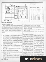
Cabinet Construction
There are several possible materials that could be employed for the cabinet. Domestic considerations, and the desire for a ready made finish dictated the use of veneered chipboard. Melamine teak board has an added advantage of being denser material than either the white or wood veneered board. These facts led to its adoption for this project. The internal volume of 2.4 cu.ft. and the desire to keep the woodworking simple determined the dimensions at 22½" x 15" x 15" external. This means that the cabinet, excluding battens, can be fabricated entirely from 15" boards. If the wood is cut to size at the timber yard the only tools required will be an electric drill and jigsaw attachment.
Assembly is straightforward and should proceed as follows:
1) Label each panel with its respective part letter on the worst face. This saves any possible confusion as work proceeds.
2) Cut the battens H, J, K, M and N to size and mark as in 1).
3) Mark out the positions of the battens on the panels with a felt tip pen. This is about the only thing that will mark the surface of the boards without smudging.

4) Glue the battens into their respective positions. The best glue to use with this material is 'Thixofix'. This adhesive is often employed for fixing table tops. It is a contact adhesive having the advantage that the glued surfaces can be moved relative to one another before they are permanently joined. A permanent joint is made by simply pressing the parts together.
5) Having fixed the battens with adhesive secure more permanently with ¾" panel pins. Use four for each batten.
6) Using the B200 template mark out the position of the four fixing screws on the front panel. Remove the central area of the template and mark the inner circle. Remove the template and drill out the mounting holes.
7) Mark out the 4¾" square cut-out for the port. At this point it is advisable to drill four 8/8" holes near the corners of the port cut-out to facilitate the use of the jigsaw.
8) Take part C and glue it into position on the baffle.
9) Cut out the front baffle apertures. The baffle can be painted matt black at this stage. Blackboard paint is suitable.
10) Take parts D and E and glue and pin together to form a square tube as shown in detail two.
11) Insert the port just constructed into the aperture on the front front baffle. If there are any gaps between the port and front panel it should be filled from the rear of the baffle. The port must be mounted so that the end is flush with the front of the baffle.
12) Take the side, bottom and top panels (A and B) and the front baffle, apply adhesive to all surfaces that will butt together, and leave for 15 minutes.
13) Assemble the cabinet except the back panel, using screws in addition to the glue to fix the front panel to its supporting battens. Check that the back panel will fit tightly in position.
14) Glue and screw the battens (L) onto the back panel (G).
15) Add the felt panels to the KEF B200's cone as previously described, then attach the drive unit to the front baffle using the bolts and T nuts provided.
16) Install the electronics. Stretch a 12" square piece of acoustic wadding across the back of the drive unit and fix it with a dab of glue in each corner.
17) After the setting-up stage, roll up 2 metres of wadding and place it in the cabinet (the position is not critical) then screw the back on.

Figure 3. Woofer cabinet construction.
(Click image for higher resolution version)
Setting Up and Use
The quiescent current of the output pair must be set to eliminate crossover distortion. Before applying power turn RV3 to its most clockwise end and cover the mains terminals of the transformer switch, and fuse with insulating tape. Apply power and if all seems well measure the voltage at the positive terminal of the output capacitor C7. This should be 20V ±2V. Switch off and disconnect the wire to the collector of TR7. Insert a multimeter to read current and switch on again. The current should be 10mA. Adjust RV3 until it reaches 30mA. Reconnect TR7. Remove the tape from the mains terminals and screw on the back of the cabinet.
Play some programme material with a good bass content. Experimentally adjust the volume control on the bass unit for what you judge to be the correct level. At this point it is as well to go and sit in the stereo seat and listen carefully. Often further adjustment will be required since the level of bass heard depends on one's listening position. The filter is best set with a voice signal.
Radio 4 is a good source of assorted voice signals. Start adjusting from the 100Hz (clockwise) end downward. Speech will probably sound a trite boomy but as you adjust a point will be found where the voice sounds natural and well balanced. Play some music, preferably a piece that you know well with a reasonable bass content. In all probability it will take some time to find the optimum position for the controls. However, even before that you should find that your enjoyment of all signals will be enhanced. It should go without saying that these adjustments should be made with the tone controls in the flat position, or better switched out.
It is most important that the woofer be sited with care. Although no stereo information is broadcast below 100Hz it is important not to disturb the stereo image. If you sit too near the woofer the sound is likely to suffer because of the Haas effect (if two independent speakers are reproducing the same signal it will appear to come from the nearer source).
PARTS LIST
| Resistors - all 5% 1/3W carbon unless specified | |||
| R1,2 | 820R | 2 off | (M820R) |
| R3,4 | 100k | 2 off | (M100K) |
| R5,6,9 | 22k | 3 off | (M22K) |
| R7 | 4k7 | (M4k7) | |
| R8 | 27k | (M27K) | |
| R10 | 1M8 | (M1M8) | |
| R11 | 120k | (M120k) | |
| R12,13 | 1K8 | 2 off | (M1k8) |
| RV1 | 4k7 log. pot, | (FW21X) | |
| RV2 | 22k lin. dual gang pot. | (FW86T) | |
| RV3 | 2k2 carbon preset | (WR82D) | |
Capacitors | |||
| C1,5,6 | 10uF 25V electrolytic | 3 off | (FB22Y) |
| C2 | 100nF polyester | (BX76H) | |
| C3 | 47nF polyester | (BX74R) | |
| C4 | 100uF 25V electrolytic | (FB49D) | |
| C7 | 2,200uF 63V electrolytic | (FF22Y) | |
| C8 | 4,700uF 63V electrolytic | (FF28F) | |
Semiconductors | |||
| TR1,3 | BC109 | 2 off | (QB33L) |
| TR2 | BC107B | (QB31J) | |
| TR4,5 | BC142 | 2 off | (QB39N) |
| TR6 | BC143 | (QB40T) | |
| TR7,8 | 2N3055 | 2 off | (BL45Y) |
| REC1 | S005 | (QL09K) | |
Miscellaneous | |||
| T1 | Transformer 240V prim 0-28, 0-28 sec. 84VA | (WB17T) | |
| LSI | Kef B200 SP1014 | ||
| FS1 | Fuse, 20mm 1A Quick Blow | (WR03D) | |
| Chassis fuseholder, 20mm | (RX49D) | ||
| S1 | Toggle switch, DPDT | (FH39N) | |
| PL1 | P429 3-pin chassis plug | (HL20W) | |
| P646 3-pin line socket | (IL44X) | ||
| 4-way push-type connector | (BW71N) | ||
| T03 Mounting kits | 2 off | (WR24B) | |
| Heatsink, 2.1° C/W | (FL54J) | ||
| Control knobs | 2 off | (RX08J) | |
| Acoustic wadding | 1m | (RY06G) | |
| Mains cable, 3A | 3m | (XRO0A) | |
| Connecting wire | 3m | (XR37S) | |
| Capacitor clip to suit C7 | (FL33L) | ||
| Capacitor clip to suit C8 | (FF35Q) | ||
| Printed Circuit Board | (GA08J) | ||
The KEF B200 SP1014 drive unit is available from:
Wilmslow Audio Ltd, (Contact Details).
Price £13.50 inc. VAT + £1.00 p&p.
CUTTING LIST
| Quantity | Dimensions (inches) | Material | Part |
|---|---|---|---|
| 2 | 15 x 15 x 5/8 | Veneered Chip | A |
| 2 | 22¼ x 15 x 5/8 | Veneered Chip | B |
| 1 | 15 x 7 x 5/8 | Veneered Chip | C |
| 2 | 11 x 3 x 5/8 | Veneered Chip | D |
| 2 | 11 x 4¼ x 5/8 | Veneered Chip | E |
| 2 | 21 x 15 x 5/8 | Veneered Chip | G |
| 2 | 20 x 2 x 1 | Soft Pine | H |
| 4 | 101/8 x 7/8 x 3/8 | Hardwood | J |
| 4 | 21 x 7/8 x 3/8 | Hardwood | K |
| 2 | 13 x 2 x 1 | Soft Pine | L |
| 1 | 13 x 2 x 1 | Soft Pine | M |
| 4 | 15 x 7/8 x 3/8 | Hardwood | N |
More with this topic
 Workbench |
 Electro-Music Engineer - Transistor Power Amplifier Surgery |
 Lab Notes - Computer Drums |
 Experimenting With Analog Delay |
 HSR Stereo Autofader Project (Part 1) |
 Sample & Hold Modification - Provides Note Bender |
 Modular Effects Rack Project (Part 1) |
 Destiny Modular Mixer - Input Module (Part 1) |
 Digital Signal Processing (Part 1) |
 Using Microprocessors (Part 1) |
 Understanding Electronics - How To Make Music Projects |
 Voice Frequency to Voltage Converter |
Browse by Topic:
Electronics / Build
Publisher: Electronics & Music Maker - Music Maker Publications (UK), Future Publishing.
The current copyright owner/s of this content may differ from the originally published copyright notice.
More details on copyright ownership...

Electronics & Music Maker - Mar 1981
Feature by Jeff Macaulay
Help Support The Things You Love
mu:zines is the result of thousands of hours of effort, and will require many thousands more going forward to reach our goals of getting all this content online.
If you value this resource, you can support this project - it really helps!
Donations for April 2024
Issues donated this month: 0
New issues that have been donated or scanned for us this month.
Funds donated this month: £7.00
All donations and support are gratefully appreciated - thank you.
Magazines Needed - Can You Help?
Do you have any of these magazine issues?
If so, and you can donate, lend or scan them to help complete our archive, please get in touch via the Contribute page - thanks!