


Magazine Archive
Home -> Magazines -> Issues -> Articles in this issue -> View
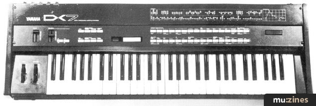
Understanding the DX7 (Part 3) | |
Article from Electronics & Music Maker, June 1984 | |
Part three, and a second took at a Yamaha factory preset. Jay Chapman takes you through it step by step.
The second of two examinations into the synthetic make-up of DX7 preset voices. This month, the program under scrutiny is 'Train'. Your conductor, Jay Chapman.

Having been led gently by the hand through the internals of E. ORGAN 1 you should now have a set of incredibly experienced digits (that's fingers, not numbers) and hopefully I can drop some of the more laboriously detailed descriptions of my keypad fumblings.
'TRAIN' has three components - the Whistle, Bell and Steam sounds. As algorithm 5 has only three carriers it's not difficult to work out which is doing what. How? Turn off each of the carriers in turn and see which part of 'TRAIN' goes away. You should end up with:
Operator 1: Whistle
Operator 3: Bell
Operator 5: Steam
Whistle
Let's deal with the interesting parts of the whistle sound. The pitch of the whistle is related to the keyboard position (as we will see, that of the bell is not) so the carrier, Operator 1, is in frequency ratio mode. The ratio is 1.64, which means that the whistle is not going to play in concert pitch but, seeing as it's a fairly unmusical sound, that doesn't matter all that much. It's when we look at the frequency ratio of Operator 2, the modulator, that some light begins to emerge, if only because it is also a bit strange at 3.03. What we are seeing is similar to the effect of a ring modulator: we can create more or less discordant sounds by modulating a carrier of a given frequency with a more or less unrelated frequency.
Confucius he say, 'one practical demo worth a lot of theoretical mumbo jumbo', so try varying the frequency ratio of Operator 2 with only Operators 1 and 2 turned on. When you get to 1.64 (remember Operator 1?) the sound becomes quite musical again. For experience you might try to get the same type of sound starting with Operator 1's frequency ratio set at 1.00. If you can't work out in advance what value Operator 2 should have for its frequency ratio parameter, just fiddle about until you get there!
On the envelope generation side of things, the carrier EG is nothing unusual. The modulator's EG has a slowish peak on the front which causes the modulated carrier's timbre to 'come and go' giving a longish 'wah' at the start of every note.
Bell
A very simple sound to make! Both carrier and modulator EGs come on like a switch and die away slowly, independently of key release. In fact, the shape of these envelopes is the same simple one used for Operator 6 on 'E.ORGAN 1' - the difference is that the Rate 2 slope is much more gentle, ie. there is a much greater time gap between leaving Level 1 and arriving at Level 2 which is zero in both cases.
The frequencies of the two Operators are not related to the keyboard. You get the same bell pitch anywhere on the upper part of the keyboard because the Operators are in fixed frequency rather than frequency ratio mode. You'll find that the frequency produced by the carrier is 371.5Hz, while that of the modulator is 977.2Hz. If you play around with the modulator frequency you'll come across lots of bell-like sounds, some of which seem more 'pure' than others. The purity, or lack of sideband frequencies, for some modulation frequency values is due to the mathematical relationship between modulator and carrier frequencies. Examples of pure and impure tones can be found with modulation frequencies of 741.3Hz (= twice 371.5Hz) and 631.0Hz respectively.
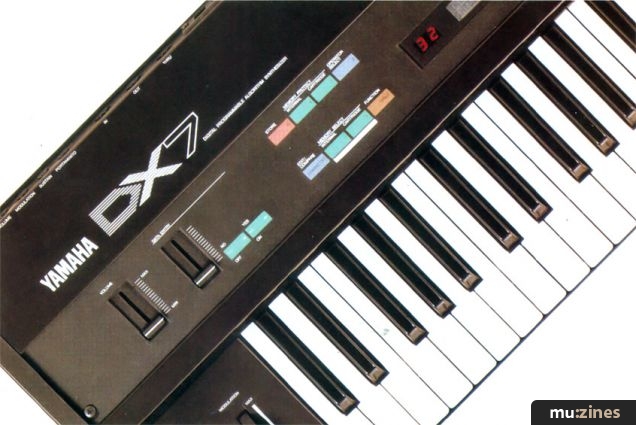
Keyboard Level Scaling
Well, well, well... I bet you had your suspicions that this subject would turn up eventually! What follows is a brief look at what keyboard level scaling is all about. The keyboard level scaling paramaters allow us to specify how we want the output levels of envelope generators compressing or expanding depending on the position of the key being pressed. We'll leave sophisticated use of this feature to a much later article although it's worth noting that it is one of the DX7 features that permit such accurate synthesis of acoustic instruments. For 'TRAIN' the feature is used very crudely to compress the whistle envelopes so that at the upper end of the keyboard they are completely flattened - they remain at zero and we hear nothing. The same thing is done for the bell at the lower end of the keyboard.
To use keyboard level scaling we must supply five pieces of information for each Operator to be affected. For 'TRAIN' we wish to affect the amplitude output by the bell and whistle components, but as we are not attempting to affect the modulation of these components (the more normal use of keyboard level scaling in imitating acoustic instruments) or the amplitude of the steam component, we need interest ourselves only in the relevant carrier Operators: 1 and 3.
Our first piece of information is related to the feature found on some synthesisers which allows the keyboard to be split into two parts. On some the split point is fixed, but on others you define it by choosing the key (or pitch) at which you wish the split to occur - the latter method is used on the DX7. In edit mode, with only Operators 1 and 3 turned on ('101000'), observe this value for each Operator by pressing the green Break Point keypad and then using the purple Operator Select keypad to view the value of each Operator in turn. You should have:
Operator 1 - Break Point = C3
Operator 3 - Break Point = C8
Whatever we do with the components, the bell's scaling will centre to the right of the top end of the keyboard and the whistle's around the bottom. Note that C3 is middle C - two octaves up from the bottom end of the keyboard - and C8 is actually three octaves above the highest C on the keyboard.
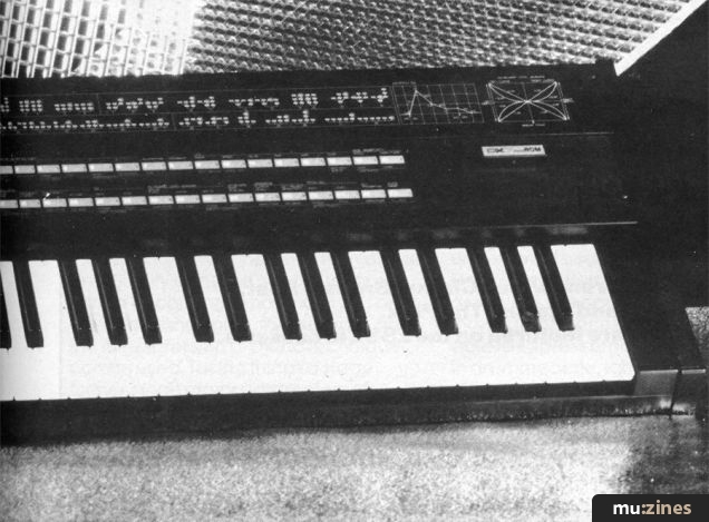
The next two pieces of information are concerned with the way the effect of scaling varies to the left and right of the break point. To understand what is going on we need to refer to the keyboard level scaling diagram Yamaha provide on the top right of the DX7 front panel.
The first thing to realise is that the vertical line marked 'Break Point' represents the key selected by the 'something like a keyboard split' choice we have just looked at. When we are deciding what to do to the left and the right of the break point key we choose from the left or right side of the vertical line, ie. we choose a 'left curve' or a 'right curve' respectively. Note that in this context a 'straight line' is just a particular type of curve, so both the LIN and EXP shapes can be referred to as curves.
When we consider left or right curves we have two more decisions to make. First, do the envelopes get compressed or expanded as we move further away from the break point? And second, is the change proportional to how far away we've moved from the break point or does the rate of change increase? The former is represented by the curves marked LIN (for linear) in the diagram and the latter by the curves marked EXP (for exponential).
A discussion of why we would choose LIN or EXP will have to wait until a later article, but suffice it to say for the moment that both the amplitude and timbre of a sound produced by an acoustic instrument have components related to the pitch of the sound, and such relationships can be approximated by the linear and exponential functions provided.
Having decided which curve to use on the left and right we must also tell the DX7 by how much each cuve is to be applied, ie. their individual depths, and these are the final two pieces of information.
So to recap, the five pieces of information for keyboard level scaling are:
1) the Break Point - where left and right curves meet.
2) the left curve's Shape.
- expand or compress
- linear or exponential
3) the left curve's Depth.
4) the right curve's Shape.
- expand or compress
- linear or exponential
5) the right curve's Depth.
Let's have a look at how 'TRAIN' uses this feature. Turn the six Operators on and press the green Depth keypad. We look at the depth before the curve type because if the depth is zero the curve is not going to have any effect and we can therefore ignore it. The display looks something like:

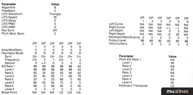
You may not have the same Operator selected (OP6) and you might have an 'R' for right instead of an 'L' for left - hitting the Depth keypad will toggle between 'L' and 'R'. By using the Operator Select keypad, cycle through the six Operators, looking at their L Scale Depth and R Scale Depth values, and you should discover that all the depth values are zero, except that Operator 1 has 'R SCALE DEPTH = 98' and Operator 3 has 'L SCALE DEPTH = 98'.
Operator 1 is the carrier for the whistle and as only its right scale is affected we hear it normally at the left-hand end of the keyboard, ie. to the left of its break point. Select Operator 1 and press the green Curve keypad until your display shows:

Looking back to the keyboard level scaling diagram, you'll see that the envelope for the whistle carrier will be more flattened the further you play to the right of its break point. If you turn on only Operators 1 and 2 - to give you the whistle on its own - and play up the keyboard from bottom to top, you'll hear the volume of the whistle stay steady until you reach middle C, after which it gradually fades the further you move up the keyboard. Figure 1 is a simplified diagram to relate the curves and their effects to the keyboard for the whistle and bell sounds.

Figure 1.
The method used for the bell sound is very similar. However, the volume of the bell drops off rapidly as you progress down from the top of the keyboard - if you consider the shape of that part of the left curve of the bell's carrier Operator that's effective you should be able to work out why.
Steam

Figure 2.
A train's steam sound shouldn't pose too many problems - we want some white(ish) noise delivered in short bursts. We already know that Operators 5 and 6 are the culprits, so let's sort them out.
Turn Operators 5 and 6 on, the rest off. Press down the green Feedback keypad and you'll see that 'FEEDBACK = 7' which is the maximum value possible. The relevant part of the algorithm diagram is shown in Figure 2.
The feedback loop around Operator 6 allows it to modulate itself, which will probably make its eyes water no end... In any case, it's very useful from our point of view as it allows us to make noise (!) To see the process in action, try varying the data slider so that the Feedback level moves from 7 to 0 and back again, and listen to the sounds produced. I'll leave you to play with the levels and frequencies at your leisure.
The last item we have to look at is how the short rhythmic 'chuffs' (note the highbrow technical terminology) are organised. Press the Speed keypad under the LFO legend. By varying the data slider you can change the frequency of the Low Frequency Oscillator (LFO) and thereby the timing of the steam sound. The LFO is used in a similar manner to most other synthesisers, so that, for example, it can provide vibrato by modulating the pitch of carrier Operators. For the steam sound, the amplitude - rather than the pitch - is modulated.
Press the green Amplitude keypad under the Mod Sensitivity legend, turn all the Operators on and select them one after the other. You will see that Operator 5 is the only Operator with a non-zero value for its Amplitude Modulation Sensitivity - in fact it has the maximum value of 3. The display showing this looks like:

What this means is that if there is any amplitude modulation going on, this Operator is going to respond to the full. The LFO is one of the amplitude modulation sources (these include the Modulation Wheel, would you believe!) so it will affect this Operator. The LFO parameter responsible for the depth of LFO amplitude modulation sent out to the Operators is shown by pressing the green AMD keypad under the LFO legend - the display looks like:

So, we have the final link in the chain producing the steam sound - with an Amplitude Modulation Depth (AMD) of 99, the LFO is modulating away at full blast. The shape of the LFO wave is a triangle (press the Wave keypad for this parameter), giving the 'chuff' we require. Try the different waveforms available by using the data entry controls.
Figure 3 shows how the steam sound would be generated using the various components of a traditionally-configured analogue synthesiser. The only thing that really changes on the DX7 is the way the white noise is produced - the VCA and EG in the diagram form part of Operator 5.

Figure 3.
Puzzle Solution
Earlier on I pointed out that the steam sound didn't go away when its carrier was turned off unless 16 more keys were pressed. You can see in Figure 3 that the envelope for Operator 5 stays on forever - this is because its envelope Level 4 has a value of 99. When a key is pressed, one of the DX7's 16 voices is assigned to that key. Since the note never finishes (because the Level 4 value won't let it) you can turn Operator 5 off and no change will occur on the voice because Operator on/off changes cannot take place on an assigned voice. When you hit the next key, a new voice is assigned which doesn't have operator 5 on and therefore has no steam sound. The original voice still hasn't stopped, however, so you still hear the steam.
The same thing happens until you have all 16 voices assigned by hitting one key (for the original voice with steam), and 15 keys more for voices without steam - 16 keys in all. When you hit another key the DX7 has a problem because it has no voices free to assign to it. It therefore decides to reassign the voice it used furthest in the past, which, in this instance, is the one still Steaming. Between the old assignment and the new, Operator 5 is set off and the steam at last runs out of puff...
Series - "Understanding the DX7"
Read the next part in this series:

Understanding the DX7 (Part 4)
(EMM Jul 84)
All parts in this series:
Part 1 | Part 2 | Part 3 (Viewing) | Part 4 | Part 5 | Part 6 | Part 7
More with this topic
 All About Additive (Part 1) |
 Technically Speaking |
 Loony Toons |
 Total recall - Cosmology |
 Add Muting, Decay/Release Isolation and/or End of Cycle Triggering to Your 4740 |
 The Poor Man's Guide to Clap Sounds |
 Advanced Music Synthesis - Inside the Yamaha GS1 & GS2 |
 Customise (Part 1) |
Rock Around the Clock |
 Back to Basics (Part 1) |
 Dave Bristow on the Yamaha DX7 - Yamaha DX Keyboards |
 The Lazy Guide To Good Synth Sounds |
Browse by Topic:
Synthesis & Sound Design
Also featuring gear in this article

BeeBMIDI (Part 3)
(EMM Aug 84)
BeeBMIDI (Part 7)
(EMM Mar 85)


Hands On: Yamaha DX7
(SOS Dec 92)

Load Baring
(12T May 85)

Load Baring
(12T Aug 85)

One For The 7 - DX7 Patch
(ES May 85)

One Off - DX7 Patch
(ES Apr 85)


Sight Reading - Yamaha DX7 Digital Synthesizer
(EMM Apr 85)

Steve Gray on the DX7
(EMM Dec 83)

The Right Connections
(ES Oct 84)

The Synths Of The Year Show - Synthcheck
(IM Dec 85)

Yamaha DX-7 Synthesiser
(MU Aug 83)
Yamaha DX7
(12T Nov 83)

Yamaha DX7
(ES Nov 83)
Yamaha DX7 Voice ROMS - Accessorycheck
(IM Jun 85)

Patchwork
(EMM Feb 84)
Patchwork
(EMM Mar 84)

Patchwork
(EMM Apr 84)

Patchwork
(EMM May 84)

Patchwork
(EMM Jul 84)

Patchwork
(EMM Aug 84)

Patchwork
(EMM Jan 85)

Patchwork
(EMM Feb 85)

Patchwork
(EMM Apr 85)

Patchwork
(EMM Jun 85)

Patchwork
(EMM Jul 85)

Patchwork
(EMM Feb 86)

Patchwork
(EMM Mar 86)

Patchwork
(EMM May 86)
Patchwork
(EMM Jun 86)

Patchwork
(EMM Aug 86)

Patchwork
(EMM Sep 86)

Patchwork
(MT Nov 86)

Patchwork
(MT Dec 86)

Patchwork
(MT Jan 87)
...and 19 more Patchwork articles... (Show these)
Browse category: Synthesizer > Yamaha
Featuring related gear

A Sound Design - Design Studio Programs
(ES Jan 85)

Delirious Xcitement - Yamaha DX7S
(SOS Mar 88)

Double Take - Yamaha DX5
(ES Apr 85)

Expand your DX
(SOS Jan 87)

Hi-Tech Xpansion
(EMM Apr 85)


Pandora's Box
(MIC Oct 89)


Russ DX7 AI Editor
(SOS Apr 88)


Temperament
(MM Apr 87)

The Fifth Dimension - Yamaha DX5
(EMM Oct 85)

The Legend Lives On - Yamaha DX7IID
(SOS Mar 87)

Tips To Tame the DX7II
(SOS Mar 88)

TX7 - To The Limit
(SOS Jun 86)


Yamaha DX5 - Synthcheck
(IM May 85)

Yamaha DX7-IID Synth
(MM Mar 87)

Patchwork
(MT Feb 88)


...and 2 more Patchwork articles... (Show these)
Browse category: Software: Editor/Librarian > Sound Design Studio
Browse category: Synthesizer > Yamaha
Browse category: Expansion Board > Grey Matter Response
Browse category: Synthesizer Module > Yamaha
Browse category: Software: Editor/Librarian > Joreth Music
Browse category: Software: Editor/Librarian > Pandora
Browse category: Software: Editor/Librarian > - (No Manufacturer)
Browse category: Software: Editor/Librarian > Steinberg
Publisher: Electronics & Music Maker - Music Maker Publications (UK), Future Publishing.
The current copyright owner/s of this content may differ from the originally published copyright notice.
More details on copyright ownership...

Electronics & Music Maker - Jun 1984
Topic:
Synthesis & Sound Design
Series:
Understanding the DX7
Part 1 | Part 2 | Part 3 (Viewing) | Part 4 | Part 5 | Part 6 | Part 7
Gear in this article:
Synthesizer > Yamaha > DX7
Gear Tags:
Feature by Jay Chapman
Ads for Gear in this article:


Help Support The Things You Love
mu:zines is the result of thousands of hours of effort, and will require many thousands more going forward to reach our goals of getting all this content online.
If you value this resource, you can support this project - it really helps!
Donations for April 2024
Issues donated this month: 0
New issues that have been donated or scanned for us this month.
Funds donated this month: £7.00
All donations and support are gratefully appreciated - thank you.
Magazines Needed - Can You Help?
Do you have any of these magazine issues?
If so, and you can donate, lend or scan them to help complete our archive, please get in touch via the Contribute page - thanks!