Magazine Archive
Home -> Magazines -> Issues -> Articles in this issue -> View
Workbench | |
Modifying The MidiverbArticle from International Musician & Recording World, December 1986 | |
Phil 'D.I.Y., Cap'n, but the engines canna take it' Walsh with a mod to turn your Midiverb into a great live tool
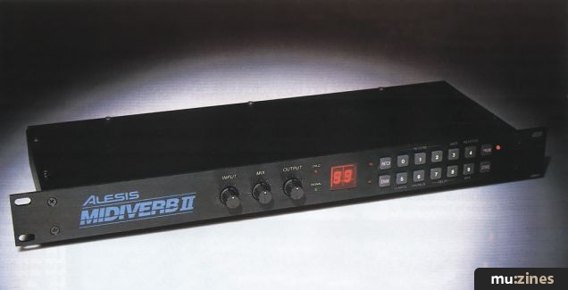
One of the best feelings in the world is to suddenly discover that you can use a piece of equipment in a way for which it was not originally designed. Despite possible comments to the contrary, I'm talking about the Midiverb (or for that matter, the Midifex) from Alesis. For the few of you who have been camping in Outer Mongolia for the past year, Midiverb is a superb digital reverb unit, having 63 preset settings, which is primarily designed for studio use. At the going rate of £395 including VAT it is ridiculously cheap. That's alright for those people who want to use one exclusively for recording but what about for live work?
I tried one out by plugging it into the send/return sockets on the back of an HH MA150 PA amplifier and found that with a bit of jiggling of the controls (more about that later) it worked brilliantly. The only thing that annoyed me was was the lack of a footswitch facility to switch the effect in and out.
Midiverb Footswitch
Fitting this to a Midiverb is a fairly straightforward job (which applies equally to the Midifex). As is my wont, I'll give you a list of parts you'll need before we go any further:-
3 off Phono Plug
2 off Mono 0.25 JackPlug
1 off Mono 3.5mm Jack Plug
1 off Mono 2.5mm Jack Plug
1 off Mono 3.5mm Jack Socket
1 off Mono 2.5mm Jack Socket
1 off Heavy Duty push to make Switch
1 off 330 Ohm resistor (0.25 or 0.25W)
1 off 0.2" LED
2 off 1N4148 or 1 N914 diode
Suitable Length (I suggest about 7 metres) of figure eight, individually screened, stereo coax
1 off case for footswitch
In order to get maximum flexibility out of the footswitch unit it would be useful to have an indicator light to show whether reverb is switched in or not. Unfortunately this is not as easy as it sounds as the type of switch used to defeat the reverb is a momentary push button. In order to get our indicator we must monitor the displays and use this information to drive our indicator. If you look at the displays you will notice that when reverb is selected the top right and/or bottom right display segment is always lit whereas when defeated only the two middle segments are lit. Luckily we can detect this using a couple of steering diodes so that the indicator will light only if one of the right hand segments is lit.

FIG 1. MIDIVERB/MIDIFEX FOOTSWITCH UNIT
So much for the theory. Figure One gives the wiring details for the footswitch — apart from ensuring that the LED is the correct way round it should present no problems. Save about 65cm of the cable for later use.
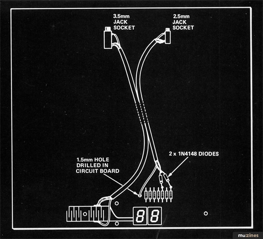
Turn the Midiverb onto its front and remove the five fixing screws. Remove the back and gently pull out the circuit board. Turn this over and position it so that the sockets are furthest from you. The part of the board nearest to you should look something like Figure Two. Now let's get vicious. On an imaginary line drawn vertically above the left hand display, drill a 1.5mm hole level with the centre line of the seven resistors. (If you hold the board up to the light you should be able to confirm that there are no printed tracks in this area). To the right of the silvery Defeat switch pad is another identical pad which is coated with green lacquer. Gently rub away the lacquer using fine sandpaper to reveal the orange copper track. Tin the top and bottom rails of the pad with solder making sure you don't get a solder bridge across the contacts. Solder the two IN4148 diodes to the first and third resistors from the right, bands towards the resistors, as shown in Figure Two.

FIG 2. TOP VIEW OF MIDIVERB/MIDIFEX CIRCUIT BOARD WITH ADDED WIRING
Cut about 25cm of the stereo cable and solder to the 2.5mm and 3.5mm sockets as shown, core to the tip connection, braid to the barrel connection. Strip back two inches of insulation at the other end of the 2.5mm socket lead and thread the core through the 1.5mm hole. Shorten the braid of this cable and then solder it to the junction of the two diodes. Insulate this joint with Sellotape to prevent any possibility of it shorting on the nearby integrated circuit. Solder the other end of the 3.5mm lead to the top and bottom rails of the switch pad. Turn the board over and the back of the displays should look as in Figure Three. Carefully identify the point labelled in the diagram and solder the core wire coming through the hole in the board to it, making sure the insulation butts right up to the joint. Drill suitable size holes for the 3.5mm and 2.5mm socket in the case top, to the left and right of the two MIDI Din sockets, just level with the top of the Din sockets. Mount the jack sockets and reassemble the case routing your wiring so that it is not crushed by the moulded rib.

FIG 3. WIRING ON UNDERSIDE OF CIRCUIT BOARD
Connecting it up
In order to use the Midiverb with standard stage gear you will need a couple of conversion leads. The first of these, used to connect the output of the Midiverb to the amplifier's echo return socket, is simply a length of coax with a phono plug on one end and a 0.25" jack plug on the other. Either output on the Midiverb can be used.
For the input, you get much more depth if you use a Y patch lead so that the signal enters both input channels. A suitable lead is shown in Figure Four.

FIG 4. Y PATCH CONNECTOR FOR MIDIVERB/MIDIFEX INPUT
In Use
Plug the Y patch lead into the amplifier's echo send socket, plugging the two phono plugs into the Midiverb's left and right input sockets. Link the other lead between the amplifier's echo return and the Midiverb's left (or right) output. Turn the Mix control on the back of the Midiverb to half-way and select an obvious reverb (eg number 50). Plug a microphone into the amplifier and whilst singing adjust the channel volume until the green LED on the Midiverb is on whenever you sing, with occasional flashes of the red LED on peaks. With the footswitch unit unplugged for the moment, check that you are getting reverb. Now plug in the two footswitch plugs and check that the display is switchable between defeat and programme 50 and also that the footswitch LED is operating correctly. If the LED does not operate then either the LED or the two diodes that you fitted are the wrong way round.
At this stage it is possible that although the footswitch appears to work perfectly, the reverb is not switched in despite what the display may tell you. Don't panic — it's just that stray capacitance in the footswitch lead is fouling things up. Simply unplug the Midiverb's power supply (leaving it switched on) and then reinsert it. You may have to do this once or twice until the problem clears. Once the problem has cleared it will work okay until the next time you set the gear up.
Everyone has their own idea of the particular vocal sound they like. As a starting point I would suggest you listen to programme 31. I set up a Boss RDD-10 Digital Delay set to give ADT and then fed this into the Midiverb (Mix half-way, programme 31). The effect was nothing short of stunning. For those of you who are interested I've drawn out the set-up in Figure Five.

FIG 5. A SET UP TO TRY
More from these topics
Plane Speaking - In Tune's Guide To Guitar Making, Customising & Setting Up (Part 1) |
Augmenting the 3750's Memory |
Reverb Modification |
Speaker Drive Units - Control Room (Part 1) |
String Attention |
Technically Speaking (Part 1) |
Guitar Routing Box (Part 1) |
Behind the Scenes |
Workbench |
Hot Wiring your Guitar |
Kit Care |
Exclusive Syn-D-Kation - The Syn-D-Kit |
Browse by Topic:
Electronics / Build
Maintenance / Repair / Modification
Also featuring gear in this article
Alesis MIDIFEX - Multiple Effects Unit
(MM Aug 86)
Alesis MIDIFEX
(SOS Aug 86)
Alesis Midifex - Studio Test
(IM Oct 86)
Alesis Midiverb
(HSR Apr 86)
Alesis Midiverb - Studio Test
(IM Apr 86)
Alesis Midiverb
(12T May 86)
Alesis Midiverb - digital reverb
(MM May 86)
Alesis Midiverb & Midifex
(12T Oct 86)
More than Meets the Eye - Alesis Midifex
(HSR Sep 86)
Reverb In Wonderland - Alesis MIDIverb
(EMM Apr 86)
Sound Effects - Alesis MIDIfex
(EMM Aug 86)
Take Two: MIDIVERB
(SOS Mar 86)
The Midifex in Brief - Alesis Midifex Preview
(HSR Aug 86)
Browse category: Studio/Rack FX > Alesis
Featuring related gear
Alesis MIDIVERB II
(SOS Jul 87)
Alesis MIDIverb III
(SOS Jan 90)
Alesis Midiverb III - Digital Reverb
(MT Mar 90)
Fourth Protocol - Alesis Midiverb 4
(MX Mar 95)
Browse category: Studio/Rack FX > Alesis
Publisher: International Musician & Recording World - Cover Publications Ltd, Northern & Shell Ltd.
The current copyright owner/s of this content may differ from the originally published copyright notice.
More details on copyright ownership...
Topic:
Electronics / Build
Maintenance / Repair / Modification
Gear in this article:
Studio/Rack FX > Alesis > MIDIVERB
Studio/Rack FX > Alesis > MIDIFEX
Gear Tags:
Feature by Phil Walsh
Help Support The Things You Love
mu:zines is the result of thousands of hours of effort, and will require many thousands more going forward to reach our goals of getting all this content online.
If you value this resource, you can support this project - it really helps!
Donations for November 2025
Issues donated this month: 0
New issues that have been donated or scanned for us this month.
Funds donated this month: £0.00
All donations and support are gratefully appreciated - thank you.
Magazines Needed - Can You Help?
Do you have any of these magazine issues?
If so, and you can donate, lend or scan them to help complete our archive, please get in touch via the Contribute page - thanks!


