


Magazine Archive
Home -> Magazines -> Issues -> Articles in this issue -> View
Destiny Modular Mixer (Part 3) | |
Power Supply And CasingArticle from Home & Studio Recording, February 1984 | |
The concluding part of this modular mixer kit.

Having previously fully described the three 'audio' modules, in this concluding look at Tim Orr's Destiny modular mixer design we turn to the power supply, the bus system and casing for the mixer, and a description of how to make the most of its facilities.
Power Supply
Although it may at first seem rather inconvenient and even untidy having the power supply in a separate box connected to the mixer via a 3 way cable, there are several very good reasons for doing so. Firstly, it keeps the profile of the mixer low and neat, it removes the problem of where to fit a mains switch and most importantly, it eliminates the hum problems associated with the transformer magnetic field and the electrostatic fields generated by the mains wiring.
The circuit for the power supply shown in Figure 1 is quite unremarkable, being a twin rail, monolithic IC regulated, full-wave rectified variety. The only 'extras' are R2, R3, C3 and C4, which keep the ripple on the voltages fed to the IC regulators low, giving the regulators a chance to attenuate the ripple voltages down to completely insignificant levels.

PSU circuit diagram.
(Click image for higher resolution version)

PSU internal assembly.
Construction of the power supply commences with bolting the L-shaped heatsink to the PCB ready for accepting the IC regulators. The PCB components should be mounted and soldered in order of height, ie. the link first, then the resistors, diodes, connector blocks and capacitors. Before soldering the IC regulators, they should be insulated from the heatsink to which they are attached using mica. Check all the soldering, and the orientation of polarised components at this stage. Once the panel hardware and transformer have been fitted inside the case, the PCB assembly can be anchored by means of the heatsink, and all the inter-wiring completed. For safety's sake double check all the routings and insulate all the mains connections using rubber sleeving.
It is advisable to test the power supply before connecting it to the mixer. This is best done using a multimeter to check the voltage on each output to 0V. Loading each output with a 47 ohm 1W resistor for a few seconds should be found not to lower the voltages significantly. The resistor will get warm though, so don't burn your fingers!
Mixer System
Since a single chassis unit will house 6 modules in all, a minimum system might consist of a single chassis unit, 4 input modules and 2 output modules, resulting in a high quality 4 into 2 mixer. A second chassis unit would allow you to add a further 4 input modules and an auxiliary module which, with the addition of a blanking plate gives an 8 into 2 mixer with headphone monitoring, auxiliary bus mixing, talkback, and all the other 'goodies' associated with the auxiliary module. You can go on expanding all the way up to an 18 into 4, consisting of 4 chassis units, 18 input modules, 4 output modules, an auxiliary module and a blanking plate. To finish any system, you will also need a power supply and a pair of wooden end cheeks.
Having decided on how many chassis units you require for your particular mixer system, the bus PCB for each chassis unit will have to be fitted with its six bus connectors. Solder them in place whilst holding them firmly down onto the PCB, then trim the excess tag length flush to the soldered joints. If more than one chassis unit is used, then the bus boards must be inter-connected using sleeved, tinned copper wire, after determining the length required. The bus boards are installed on spacers in the chassis units with the lettering and the four thin tracks towards the front. First though, the DC supply cable must be terminated on the right hand bus board. The free end of the cable is then fitted with a 3 pin DIN plug for connection to the power supply.
The chassis sections bolt together quite neatly, and are finished on the front with 'comfy' rexene covered wooden handrests, which are screwed on from inside the chassis unit. The end cheeks are screwed on similarly at either end. All that remains is to stick on the rubber feet so that the completed chassis is ready to accept the selected modules. When fitting the modules, the rear PCB extension slips under the rear panel lip, and the jack bushes engage in the appropriate rear panel holes. Raise the module so that the jack bushes are against the top of the elongated holes, then line up the bus connector and push firmly, but carefully home. A couple of screws in the top, and the jack nuts on the back will hold the module tightly in place. White plastic strips are thoughtfully provided to place below the faders and/or above the module for temporary 'wipe-off' marking of channel designations, etc.

Modules plugged into the buses.
Once all the modules are in place, connect the mixer to the power supply and switch on, again checking the output voltages if possible. Put each module through its paces, making sure that each function is working properly.
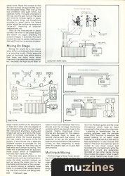
Mixing On Stage
Mixing the sound for a live music show differs considerably from mixing in a recording studio. Firstly everyone plays at the same time which means that there are many more mixer channels to be balanced and equalised etc. Secondly the high sound level on stage makes it difficult for the players to hear each other with any degree of sound balance. Figure 2 shows how all the instrument amplifiers, drums and singers are set-up and fed to the mixer which is normally positioned in the audience where the sound engineer can hear clearly the sound of the PA system. It also shows how a separate foldback system is provided for the players on stage, so that they can all hear what each person is playing. This other mix is derived from an auxiliary mixer output which is independent from the main stereo PA mix.

Stage mixing.
The mixer also adds effects to the overall sound, such as reverb and echo, using the other auxiliary outputs as well as taping the stereo mix for the inevitable post-mortem of the concert. Live sound mixing is certainly more liable to problems than studio recording, the most common one being feedback or howl-round between the microphones and the on-stage monitoring systems which are placed close to the players. Highly directional microphones are favoured for this reason. Also, because there is never any second chance with live sound, it is essential to set up the system and balance the sound before the audience arrives, so that everything is ready when the players walk on to give their performance.
Multitrack Mixing
The first stage of most music recording involves laying down on tape the basic rhythm structure. This usually means drums and bass guitar, along with a rough 'guide' track of vocals to help the rhythm players through the song's arrangement. Figure 3 shows four microphones set up around the drum kit, the bass guitar and the vocal microphone which have all been connected to the mixer input channels.

Laying down rhythm tracks.
Listening on headphones, the recording engineer uses the pre-fade listen (PFL) function to examine the sound coming in on each mixer channel, to check that all is well and to add equalisation to any sounds that need it. The drum microphones are all routed to one mixer output and recorded onto one tape track, while the bass and vocals are separately recorded on two other tracks. During this process the players listen to each other using headphones driven from one of the auxiliary outputs of the mixer which allows them a balanced mix of what is being recorded onto tape.
Next comes the addition of the other instrument sounds like guitars, keyboards and vocals, but because of the limited number of tracks available on tape, some track bouncing will be needed. Figure 4 shows how the mixer may be used to bounce three tracks down to the one remaining track, which then makes room for three new tracks. In this way the recording is built up layer by layer until all the necessary ingredients of the sound are on tape and ready for the final 'mix-down'.

Bouncing down.
In the final stage of the recording process the four tracks are mixed down to a two-channel stereo format which necessitates the use of a second tape recorder. Figure 5 shows how the mixer is used to transfer the sound across from one recorder to the other, and in doing so it allows a number of useful enhancements to be made for the final result.
Firstly there is the question of attaining the right balance between the four tracks and the position of each track within the stereo sound image using the pan pots. Final alterations are also made to the equalisation of each track to highlight the overall tone quality, and there is a further opportunity to add special effects such as reverberation, echo, chorus and phasing etc. The auxiliary mixer outputs are used to send any mixture of the sounds to these effects, whose outputs are then brought back on the remaining mixer input channels.

Mixdown.
Finally the end result is reached with a stereo tape that may be played on any domestic sound system. Improvements in technique come with practice, and care is taken to ensure that maximum level goes onto tape wherever possible. It is also a good idea to keep the signal levels within the mixer as high as possible to optimise the signal to noise ratio. Adjusting the input channel gain controls so that the +4dBm LEDs just flicker on the loudest passages will achieve this.

Completed chassis and modules.
The Kits
The kits supplied for review were found to contain good, high quality components throughout, most of the resistors being high stability 2% types. The panelware and screen printing was also found to be of a very high standard. Several parts were missing from the review kits, although hopefully this is not representative of the production kits. The kits were not quite complete in that wire, cable and solder had to be provided by the constructor. The handbook is also a little light on constructional details, so this series of articles should be found quite useful in that respect.
Considering the ease of construction, the very high standard and versatility of the design, and the quality of the components, these kits represent excellent value for money, and can be highly recommended.
The Destiny mixer is available from Powertran, (Contact Details).
Prices are as follows: Input module £19, Output module £18, Auxiliary module £21, Base unit & wooden front £26, pair mahogany end cheeks £11, Power Supply £19. Please add VAT and quote reference number HD100 when ordering.
Series - "Destiny Mixer"
This is the last part in this series. The first article in this series is:

Destiny Modular Mixer
(HSR Dec 83)
All parts in this series:
More with this topic
 Equally Tempered Digital to Analog Converter |
 The Spectrum Synthesiser (Part 1) |
 Amdek DMK-200 Delay Machine Kit |
 HSR Stereo Autofader Project (Part 1) |
 Add Muting, Decay/Release Isolation and/or End of Cycle Triggering to Your 4740 |
 The Spectrum Synthesiser - Professional Quality Monophonic Instrument (Part 1) |
 Studio Project - Going Direct |
 Voltage Controlled Clock |
 Soldering On (Part 1) |
 Workbench - Signal Processors — the saga continues |
 Hot Wiring your Guitar |
 Confessions - ...of an English kit builder. |
Browse by Topic:
Electronics / Build
Publisher: Home & Studio Recording - Music Maker Publications (UK), Future Publishing.
The current copyright owner/s of this content may differ from the originally published copyright notice.
More details on copyright ownership...

Home & Studio Recording - Feb 1984
Donated & scanned by: Mike Gorman
Feature by Paul Williams
Previous article in this issue:
Help Support The Things You Love
mu:zines is the result of thousands of hours of effort, and will require many thousands more going forward to reach our goals of getting all this content online.
If you value this resource, you can support this project - it really helps!
Donations for April 2024
Issues donated this month: 0
New issues that have been donated or scanned for us this month.
Funds donated this month: £7.00
All donations and support are gratefully appreciated - thank you.
Magazines Needed - Can You Help?
Do you have any of these magazine issues?
If so, and you can donate, lend or scan them to help complete our archive, please get in touch via the Contribute page - thanks!