


Magazine Archive
Home -> Magazines -> Issues -> Articles in this issue -> View
Understanding Electronics | |
How To Make Music ProjectsArticle from Electronics & Music Maker, May 1982 | |
A regular column that explains the electronics of music
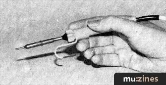
A soldering iron with small bit.
If you have never constructed an electronic project, building even one of the more simple ones described in this magazine may seem a daunting task. While it would be misleading to suggest that without any previous knowledge of electronics or practical experience at electronics construction it would be possible for anyone to build any project, it is a fact that anyone who is reasonably practical should have little difficulty in successfully completing a relatively small project. This article is aimed at those who would like to build their own equipment but need a little encouragement to get started.
Many people are deterred from building an electronic project simply because they do not understand the way in which the circuit operates, but it is not really necessary to understand the technicalities in order to successfully build it. Technical knowledge can be helpful when fault finding, but is otherwise not of great importance when constructing projects.
Undoubtedly the greatest asset to have when project building is practical experience of electronics construction, and obviously the only way of obtaining this is to 'take the plunge' and try your hand at building a few small ones. Most people rapidly learn the few simple skills required, and have no difficulty in building quite complex pieces of equipment.
A point that should not be overlooked is that project construction is an interesting and enjoyable pursuit in its own right, and should not simply be regarded as a cheap way of obtaining items of electronic equipment.
Getting Started
The first thing to do when considering any project is to read the article thoroughly to ensure that the finished piece of equipment is capable of fulfilling your requirements — a 12V 50mA power supply will not be much use for recharging flat car batteries. Having decided to go ahead, any points that are not fully understood should be resolved when the components have been obtained. Do not commence building until you understand all aspects of the construction.
Tools
Only a few tools are required for the electronic part of the construction; a 15 to 25W soldering iron, side cutters, long nosed pliers, wire strippers and in case of errors some form of solder remover, e.g. copper braid, solder sucker, or desolder tool.
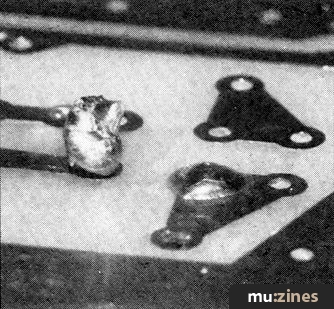
Example of a bad (left) and a good (right) solder joint.
More tools are required for the mechanical parts but these are the type that most people will already possess; screw drivers, adjustable spanner, junior hacksaw, files, drills etc.
There are two important facts to remember when purchasing tools; always buy good quality, cheaper versions are a false economy and secondly apart from the basic tools buy any others as you require them, it is very easy to spend a great deal of money on tools that are never used. And while we are on this subject, do not use tools for any task other than they were intended; a colleague's ultimate test for a small pair of side cutters was if they could cut through the plastic spindle of a potentiometer! (Anyone want to buy half a pair of side cutters?).
Work Area
For the construction of the electronics an area approximately 1m x ½m is required. It is not essential to use a proper workshop bench and the wife's or mum's kitchen worktop will suffice. However, it is advisable to cover this with a sheet of plywood to avoid damage to the worktop and the subsequent naggings.
Modern electronic components tend to be quite small and are easily mislaid or lost. So in order to stop the frustrated crys of "well it can't just of disappeared!", use the readily available small plastic draws or small tins to store your components. An alternative is to use a piece of expanded polystyrene into which the component leads or tags can be inserted.
The mechanical construction is best carried out at a proper workbench, otherwise the naggings could develop into eviction or divorce.

Tinning the bit.
Circuit Boards
Most projects these days are based on a printed circuit board of some kind. The usual single sided board simply consists of a thin piece of glassfibre board (other materials such as S.R.B.P. are sometimes used) in which holes for the leadout wires of the components have been drilled, and there are areas of copper on one side of the board. The components are fitted on to the plain side of the board, the leadout wires are trimmed almost flush with the underside (copper side) of the board, and then the leads are soldered to the copper tracks. The latter carry the appropriate interconnections between the components.
There should be little difficulty in identifying the components and fitting them on to the board correctly. There are a few things here that must be understood, such as resistor and capacitor colour codes, and these have been covered in previous parts of 'Understanding Electronics'. Ready-made printed circuit boards usually have the component layout marked on the appropriate side of the board, complete with the polarity of any electrolytic capacitors (which must be fitted on to the board the right way round) and any other necessary information, which greatly reduces the risk of mistakes being made.
It is not difficult to make your own printed circuit boards at low cost, and this will be covered in a future 'Understanding Electronics'. However, when building the first one or two projects it is best to use a ready made printed circuit board.
Many projects are based on a proprietary form of printed circuit board generally known as 'stripboard'. This type of board is drilled with a matrix of small holes with a hole spacing of 0.1in or 0.15in, the former being by far the more popular these days. Strips of copper run across the underside of the board and carry the connections between components, like the copper tracks of an ordinary printed circuit board.
Whereas an ordinary printed circuit board is normally designed for use with a single project, and could not easily be used for any other circuit, stripboard can accommodate any circuit. Stripboard often has a cost advantage over an ordinary printed circuit board, but is perhaps a little less easy to use and gives a slightly less neat appearance.
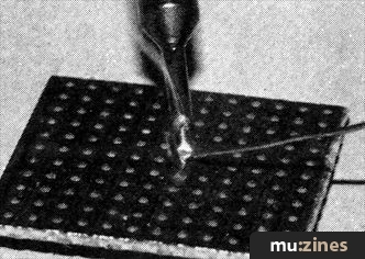
How to solder.
In use stripboard is slightly different as it is usually necessary to cut down a board to the required size, and this is easily done using a hacksaw to cut through a row of holes rather than between them. This is likely to give cut edges having a rather rough finish, but a file can be used to smooth these. Most designs require breaks to be made in some of the copper strips, and the positions of these breaks will be clearly shown in a drawing of the underside of the board. A special cutting tool is available, but it is quite in order to make these breaks using a small twist drill of about 4mm in diameter, or a modelling knife. Whatever you use, make sure that the break covers the full width of the copper strip, and avoid damage to other copper strips.
Soldering
For soldering components to a printed circuit board a soldering iron having a power rating of about 15 to 25 watts and a small (say about 2.3 or 2.4mm diameter) bit is ideal. This will also be suitable for soldering leads to controls and sockets. It is unusual for a modern electronic project to have large soldered joints, and you are unlikely to ever need a powerful iron having a large bit. The solder normally used for electrical connections is a resin cored, 60% tin, 40% lead type, and most component retailers supply this in two thicknesses. The majority of constructors prefer the thinner 22 swg type to the 18 swg solder, but either type is suitable.
Before trying to solder the components on to a printed circuit board for the first time it would be advisable to try soldering a few odd pieces of wire together, or perhaps trying to solder a few bits of wire to a piece of stripboard would give some useful and inexpensive initial experience.
It is a good idea to have a proper stand for the soldering iron as this will help to prevent it from overheating as well as providing a safe place for it. There is no need to panic if the iron gives off a certain amount of smoke when it is first switched on, this is merely a protective coating burning off the bit. The bit needs to be tinned with solder, and this simply entails applying a small amount of solder to the end of the bit. Again, there is no need to get alarmed if a certain amount of smoke is produced as this is simply the cores of flux burning away. The flux helps the solder to flow over the surfaces which are to be joined so that a strong joint is produced.
When making a soldered joint do not try to apply the solder to the bit and then to the joint. Apply the tip of the bit to the joint and then feed in sufficient solder to produce a strong and reliable connection. If you use too little solder it is likely that it will not flow off the iron and on to the surfaces to be joined. Too much solder is likely to result in 'blobs' of solder short circuiting adjacent copper tracks, and any excess solder must be removed.

A piece of stripboard.
Ideally you need four hands when soldering: one to hold the iron, one to feed in the solder, and one to hold each of the two items to be joined. With a little practice you will soon learn to cope without plastic surgery, the easiest way being to lay the component board copper side up on the workbench with the component to be soldered in place trapped under the board. This method works fine provided you start with components like small resistors which do not protrude far above the board, and gradually solder in the larger components. If this is not done it is likely that the small components will not fit flat against the board, and apart from looking untidy this is not a very sound method of construction since any pressure on the components could lift and break the copper tracks on the underside of the board. Do not feel that you have to use this method, tackle the problem in any way you find easy and convenient.
Soldering leads to the tags of controls and sockets is quite easy if you generously tin both with solder first. With the bit also well tinned with solder, placing the end of the lead in position on the tag and briefly applying the iron should produce a good joint without the need for any additional solder.
When stripping the plastic insulation from connecting wire always use a pair of wire strippers, and not scissors or a knife. This avoids nicking the wire (which would severely weaken it and probably lead to it breaking before long). It is usually better to use multi-strand connecting wire rather than the single core type which is far less flexible. The single coretype is mainly used in large projects where a number of leads are grouped together and are shaped to neatly run from one part of the unit to another.
Mechanical Construction
The majority of projects are housed in a metal or plastic case. When deciding upon which one of the many available to use, consider what controls, plugs, sockets etc are to be mounted and their most practical position. Also since the case is often the most expensive item, try to avoid the false economy of buying the smaller of the possibles. Better to err on the large size so that there is ample room in which to wire the components and perform any repairs.
Applying gentle pressure with the left boot to squeeze everything in is definitely not on!

Layout of a small project inside its case.
Printed circuit boards are sometimes designed so that they slot into guide rails moulded into the case specified for the project, and in such cases you will probably run into difficulties if you use an alternative housing. The common method of mounting the printed circuit board is to simply bolt it in place. It is normally necessary to use extra nuts or spacers (which are simply small pieces of metal tubing) over the mounting bolts between the case and the board so that the underside of the board is kept clear of the case. Sometimes this is necessary because a metal case is employed for the project and allowing the underside of the board to touch the case would result in the copper tracks being short circuited. Even if a non-metallic case is used it is advisable to use a small amount of spacing, otherwise the board may buckle slightly as the mounting nuts are tightened, due to the soldered connections protruding on the underside of the board.
An alternative and neat method of mounting a printed circuit board is by using plastic stand-offs. The stand-offs plug into holes of the appropriate diameter drilled in the case, and then the printed circuit board is clipped on to the stand-offs. This enables the board to be easily and quickly mounted or dismounted from the case.
The mounting holes for the printed circuit board must be positioned fairly accurately or at best the finished article will look rather scrappy, and at worst the circuit board will refuse to fit in place. Using the printed circuit board as a template helps to minimise any errors, and when drilling any sort of mounting hole it is advisable to first drill a small guide hole and then drill this out to the correct size.
Many types of control and socket have a built-in 10mm diameter mounting bush, and require a single 10mm diameter mounting hole. A 10mm twist drill is one size that it is essential to have, and you will find that quite a variety of other sizes are required from time to time. Sometimes rectangular or irregular shaped cutouts are needed, and a set of miniature files are then likely to prove invaluable.
Most controls are fitted with long spindles that will normally have to be trimmed down to a more suitable size. This is easily done by gripping the spindle in a vice and then cutting the spindle at the appropriate point using a hacksaw. Do not grip the body of the component in the vice as this could easily damage the component, and the spindle may tend to rotate as it is sawn through.
And Finally...
When you choose your first constructional project try not to be over ambitious, and select something reasonably simple where there is relatively little opportunity to make mistakes. It is also advisable to choose a battery powered project rather than a mains powered one. If a mistake is made in a battery powered project it is unlikely to cause any damage or be at all dangerous, and you can search for errors in complete safety even when unit is switched, on.
More with this topic
 Electro-Music Engineer - Tuning Up — A Review of VCO Calibration Methods (Part 1) |
 Studio Earthing Techniques - Interconnect (Part 1) |
 Hexadrum |
 Workbench - Remote Control System |
 An Ultra VCO From The 4720 |
 X-Ray Specs - Ben Duncan explains the language of the specification sheet (Part 1) |
 Build A Hum Loop Isolator |
Projected Developments |
 Hot Wiring your Guitar |
 An Emulator for £10 |
 Workbench - STAGE LIGHTING INTERFACE BOARDS |
 Speaker Drive Units - Control Room (Part 1) |
Browse by Topic:
Electronics / Build
Publisher: Electronics & Music Maker - Music Maker Publications (UK), Future Publishing.
The current copyright owner/s of this content may differ from the originally published copyright notice.
More details on copyright ownership...

Electronics & Music Maker - May 1982
Feature by Robert Penfold
Help Support The Things You Love
mu:zines is the result of thousands of hours of effort, and will require many thousands more going forward to reach our goals of getting all this content online.
If you value this resource, you can support this project - it really helps!
Donations for April 2024
Issues donated this month: 0
New issues that have been donated or scanned for us this month.
Funds donated this month: £7.00
All donations and support are gratefully appreciated - thank you.
Magazines Needed - Can You Help?
Do you have any of these magazine issues?
If so, and you can donate, lend or scan them to help complete our archive, please get in touch via the Contribute page - thanks!