


Magazine Archive
Home -> Magazines -> Issues -> Articles in this issue -> View
Mixer Basics | |
Article from Recording Musician, January 1993 | |
A step-by-step guide to the workings of a typical mixing console.
The mixer is unarguably the most important piece of equipment in the studio, and a proper understanding of its operation is vital. Paul White begins a guided tour of the inside and outside of the mixing desk.
In principle, the mixing console is pretty straightforward, but the very size of some mixers can make them appear somewhat daunting. Though they come in all shapes and sizes, the underlying principles are surprisingly similar, and the concepts embodied in a Portastudio's mixing section also apply to studio consoles the size of a room.
At their simplest, mixers combine two or more audio signals and allow their levels to be independently adjusted. More refined designs include equalisation (a fancy term for tone controls), the provision to connect up external effects units (such as reverberation or echo) and the ability to route or switch signals and mixes of signals to different destinations. Why all this should be so will become apparent shortly, but to start with, I'll describe a simple, four-channel mixer which could be used to mix four signals into one. Because the mixer has only one output, the output signal in this case will be mono. For stereo, we require two signal paths, one to carry the left speaker signal and one to carry the right speaker signal.
You may recall that when we were discussing tape recording (Multitrack Basics, RM September 1992), I pointed out that all electronic circuitry has an optimum operating range. If the input signal exceeds this range, distortion will result, while if the signal falls too far below it, the amount of amplification required to bring it back up to a usable level will also make it noisy. Mixers are no exception, and their internal circuitry is designed to work within a particular range of signal levels, usually up to 10 or so Volts. Some signals are already within this range, such as the outputs from effects units and some electronic instruments, but the signal produced by a microphone may measure only a few thousandths of a Volt, clearly making it too small. To get around this problem, any mixer designed for use with microphones will incorporate a special, low-noise microphone amplifier, right at the input, which brings the microphone signal up to the mixer's internal working level. This microphone preamplifier may also be fitted with phantom power circuitry enabling it to be used with capacitor microphones (see box).
Because not all microphones produce the same level of output, and because the output level depends on how close and how loud the sound being recorded is, the microphone amplifier is invariably equipped with a gain control which determines the amount of amplification applied to the signal. In other words, the setting of the gain control relates to how much bigger the signal will be made. Signals that don't need to be passed through the microphone amplifier are said to be line-level signals, though this is a rather vague term and tends to cover anything from around a quarter of a Volt up to 10 Volts or so. Because the level varies so much, the Line input on a typical mixer will also be fitted with a gain control. On the majority of professional mixers, the microphone and line inputs will each have their own gain control, but on most home recording and semi-pro recording and mixing equipment, a common control is used for both mic and line gain adjustment.
Mixer Topography
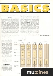
Figure 1 shows a simplified schematic of a 4-channel, mono mixer with simple bass and treble equalisation. Separate Mic and Line gain controls have been shown to aid clarity, but in practice, a single, shared control is more likely on a mixer of this type. There are separate input sockets for both the microphone and line input signals though, again, on budget equipment it is possible that a single socket will be used for both. A switch is used to select between the microphone input and the line input; it is not normal to be able to use both at the same time, though some designs do permit this. Directly after this switch comes the equalisation section, which can be as simple as the bass/treble (also known as Hi\Lo) arrangement shown here or can be a complex, multiband affair, as is more common in serious semi-pro and professional mixers. More sophisticated mixers have an additional switch allowing the equalisation section to be bypassed when not in use.

Figure 1: Simple 4-channel mono mixer.
Finally the signal level is controlled by a fader before it passes through a switch onto the mix buss. This switch, if fitted, may be called On or Mute depending on the manufacturer. Note that all four input channels are identical, and a larger mixer simply needs more input channels.
Though the diagram shows the individual channels being connected directly to the mix buss, the reality is a little more complex, though it need not concern us at this point. Suffice it to say that under normal circumstances, it is not possible to mix signals simply by connecting the outputs of several different pieces of equipment to a common piece of wire; specialised mixing circuitry is essential — which is why we need to use a mixer.
The combined signal on the mix buss passes through further amplification stages (known as the mix amplifier) controlled by the Master Level Fader. This controls the output level of the mixer, allowing it to present the correct signal level to the amplifier or tape recorder being fed by the mixer. The master fader is also used to make controlled fades at the end of songs.
Stereo
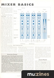
It only requires a few small changes to turn our hypothetical mono mixer into a stereo one. Figure 2 shows a schematic that is in many ways similar to that in Figure 1, except that the input channels have an extra control — the Pan control. This is used to direct the channel signal between two mixing busses, one being used to carry the left signal and the other to carry the right. When the pan control is turned completely anti-clockwise, the channel signal is routed exclusively to the left mix buss; turning it clockwise routes the signal to the right buss. Leaving the pan control in the centre routes equal amounts of signal to the left and right busses, making the resulting sound (when reproduced over a stereo speaker system) appear to emanate from the centre. These two busses are often referred to in the singular as a stereo mix buss, though in reality, the two busses are physically separate.
Note that we now have two master faders, one for the left and one for the right signal, though some mixers use a ganged control with a single knob to save on cost and space.

Figure 2: 4-channel stereo mixer.
Figure 2 also includes a stereo level meter, which allows the user to monitor the output level of the mixer. This will be familiar to anyone who has used a stereo cassette recorder, though the mechanism could take the form of a moving-coil meter with a physical pointer or it could be a row of LEDs (Light Emitting Diodes) arranged in the form of a ladder.
This type of simple stereo mixer is very common for use in small PA (Public Address) systems, and its format is usually described in the form 'something' into two; for example, a twelve into two (12:2) mixer has twelve input channels and two (left and right) outputs.
Auxiliaries
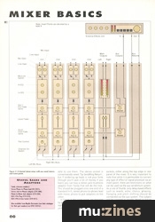
On top of the features already mentioned, most recording mixers have some facility for connecting external effects and for producing an alternative cue or monitor mix for the performers. In a live situation, the cue mix would be fed to the stage monitors and may well have a different balance of instruments and voices to the main mix heard by the audience. This is necessary when, for example, the performance includes complex vocal harmonies and the singers need to hear more of the vocals than of the instrumental backing. Both effects and cue monitoring can be handled using the auxiliary controls on a mixer. To understand how these work, take a look at Figure 3. Here you can see two new controls: Aux 1 and Aux 2 — aux being a shortened form of auxiliary.

Figure 3: 4-channel stereo mixer with aux send/returns and insert points.
Aux 1 is simply another level control feeding a mono mix buss which runs across the mixer to the Aux 1 Master level control and then to the Aux 1 output socket. The signal feeding the Aux 1 control is taken before the channel fader and is known as a pre-fade send. The significance of this is that, once set, the level of the Aux 1 signal doesn't change if the channel fader setting is varied. It follows that a mono mix of all four channels can be set up using the Aux 1 controls, and this will appear at the Aux 1 Master output under overall control of the Aux 1 Master level control. This mix, being totally independent of the main fader settings, can provide the performers with a monitor mix that is exactly to their liking without compromising the main stereo mix.
The other aux control, Aux 2, is located after the channel fader (post-fader) and, as a consequence, its level is affected by changes in the fader setting.
This is exactly what we need if Aux 2 is being used to feed an effect such as reverb because, as the channel fader setting is changed during the course of a mix, the amount of effect will change by the same amount, maintaining the correct balance of effect to dry signal. By using different settings of the Aux 2 control on each channel, it is possible to send different amounts of each channel's signal to the same effects unit.
When the output from this effect unit is added to the main stereo mix, this has the advantage that different amounts of the same effect can be added to different sounds in a mix. A typical example might be where one reverberation unit is used to provide a rich reverb for the vocals, less reverb for the drums and little or none for the guitars and bass.
It is important to note that an effects unit used in conjunction with a channel aux send should be set up so that it produces only the effected sound and none of the original. This is usually accomplished by means of a mix control, which is either in the form of a knob or accessed via the effects unit's editing software. In either case, the mix should be set to 100% effect, 0% dry.
The output of the effects unit may be fed back into the mixer via spare input channels or via dedicated effects return inputs, also known as aux returns. Aux returns are electrically similar to the input channels but usually with far fewer facilities; they have no mic inputs, little or no EQ and few, if any, aux sends of their own. Normally they feed straight into the main stereo mix. If, however, a spare input channel is used to feed an effect output into the mix, ensure that the corresponding aux send (in this case Aux 2) is turned down on that channel or the effect signal will be fed back on itself, resulting in an unpleasant howl or scream.
Since many effects units have stereo outputs, they need to be connected to either two spare input channels or to a stereo aux return input. The diagram in Figure 3 shows an external effects unit connected to the stereo Aux return, where the two inputs feed the left and right stereo mix busses.
Note: Though the controls shown in the figures are arranged in a logical order to illustrate the signal flow through the channel, commercial mixers tend to have the pan and aux controls located above the channel fader.
Insert Points
Finally, there is another way to connect an effects unit or signal processor to a mixer, and that is via an Insert Point. All serious mixers have insert points on the input channels and also on the master stereo outputs, an insert point simply being a connector that allows the normal signal path to be interrupted and re-routed through an external device. On most of the mixers you are likely to encounter, the insert points will be in the form of stereo jack sockets, which means you need a specially wired Y-lead or adaptor to be able to use them. The stereo socket is conventionally wired 'Tip Send/Ring Return', but if soldering up leads is not your forte (though you'll save a lot of money if you learn) you can buy a stereo jack-to-phono adaptor from Tandy that will do the trick. This should be plugged onto one end of a standard hi-fi, stereo phono-to-phono lead with mono, phono to jack adaptors on the other.
In Figure 3, the insert points are depicted by bold Xs which show their position in the signal path. Physically, they appear as stereo jacks and are located with the other sockets, either along the top edge or rear panel of the mixer. It is very important to note that while it is permissible to connect any type of effect or signal processor via an insert point, there are restrictions on what can be used via the aux send/return system. As a rule of thumb, only delay-based effects such as reverb, echo, chorus, phasing, flanging and pitch shifting should be connected via the aux system. This subject will be covered in greater depth in future issues of RM. Next month, I'll be continuing with a look at recording consoles and their facilities.
Key Terms
| EQUALISATION | Recording term for tone control. Usually comprises treble, mid and bass. |
| GAIN | The mixer gain control determines the amount of amplification applied to a signal - put simply, a recording term for volume. |
| PAN | Short for panoramic. This control allows you to move sounds left and right in the stereo sound stage. |
| INSERT POINT | A connector that allows the normal signal path to be interrupted and re-routed through an external device, such as a compressor. |
| BUSS | Piece of circuitry or wiring connecting several parts of a system. In the context of a mixer, busses are used to 'collect' the outputs from the various channels and mix them together. A mixer may have several busses carrying the main stereo mix, the aux sends and — on more sophisticated recording mixers — sub-mixes of different groups of channels. |
| DRY SIGNAL | A sound source which has no added effect. Conversely, a sound treated with an effect such as reverberation or echo is often referred to as wet. |
| LINE LEVEL | Mixers and signal processors tend to work at a standard signal level known as line level. In practice, there are several different standard line levels, but all are in the order of a few volts. Microphones produce a much lower signal, in the order of tens of millivolts. |
Phantom Power
In theory, it is quite safe (though pointless) to apply phantom power to a dynamic microphone, so long as it is wired for balanced operation, as the same voltage will appear at both ends of the voice coil — which means that no current flows through it. The reason I mention this is that some budget mixing consoles have a global phantom power switch, so if you intend to use both dynamic and capacitor mics on the same session with such a console, you have to ensure that all cables are balanced and that the mics are internally wired for balanced operation. As a rule, if the mic body is fitted with a three-pin XLR socket, it is balanced, but always check the data sheet that came with the mic to be sure. Use of unbalanced cables might cause damage to dynamic mics, as could plugging or unplugging them with the phantom power turned on.
Useful Leads and Adaptors
Stereo Phono-to-Phono lead (42-2351).
Stereo Jack-to-Phonos adaptor (274-308).
Phono-to-Mono Jack adaptor (274-320).
XLR 3-Pin Plug (274-010).
XLR 3-Pin In-Line Socket (274-011).
Also available from Maplin Electronics (see their catalogue for their part numbers) on (Contact Details).
More with this topic
 Mixing Essentials - Mixing in the MIDI Age (Part 1) |
 Hands On: Soundcraft Spirit Studio Mixer (Part 1) |
 Steal The Feel (Part 1) |
 We Can't Go On Metering Like This! |
 Mixing for the Small Gig (Part 1) |
 Speaker's Corner - CHOOSING & USING: studio monitoring |
 The Explosive Mixture - The First Single |
 Monitoring - Sound Workshop |
 Mixdown Lowdown (Part 1) |
 Sound Bites - Production Tips & Techniques |
 Insider Fading - Behind The Design Of The Soundcraft DC2000 Moving Fader Console |
 Home Recording: Frequency Balancing |
Browse by Topic:
Mixing
Publisher: Recording Musician - SOS Publications Ltd.
The contents of this magazine are re-published here with the kind permission of SOS Publications Ltd.
The current copyright owner/s of this content may differ from the originally published copyright notice.
More details on copyright ownership...

Recording Musician - Jan 1993
Donated & scanned by: Mike Gorman
Feature by Paul White
Help Support The Things You Love
mu:zines is the result of thousands of hours of effort, and will require many thousands more going forward to reach our goals of getting all this content online.
If you value this resource, you can support this project - it really helps!
Donations for May 2026
Issues donated this month: 0
New issues that have been donated or scanned for us this month.
Funds donated this month: £0.00
All donations and support are gratefully appreciated - thank you.
Magazines Needed - Can You Help?
Do you have any of these magazine issues?
If so, and you can donate, lend or scan them to help complete our archive, please get in touch via the Contribute page - thanks!