


Magazine Archive
Home -> Magazines -> Issues -> Articles in this issue -> View
Amdek Compressor Kit | |
Article from Electronics & Music Maker, January 1983 | |
A versatile sound processor kit for keeping musicians' playing levels in check

This month we continue our Amdek series with the Compressor, another useful effect which can be assembled and customised with the minimum of technical difficulty.
The Compressor is a useful addition to any Electro-music studio. In recording applications it can be used to reduce the dynamic range of input signals or in PA situations it could be used to stabilise often unpredictable microphone signals.
Parts Cost Guide £28
* Automatic Level Control
* LED effect on and battery check indicator
* Pre-assembled circuit board
* Complete kit with detailed instructions
The unit compresses the sound by boosting small signals and attenuating larger ones. This is demonstrated in Figure 1. The input, A, has a percussive envelope, such as that produced by a guitar, which, when processed by the circuit, results in the compressed output (shown dotted). The initial high peak, B, has been reduced and the decaying input is boosted to a sustain level, C.

Figure 1. Output characteristics of the Compressor.
The box has two controls, output Level, and Sustain level with the facility to use an optional external power supply.
The Kit
The Compressor is supplied in the usual bubble pack, complete with all parts, connecting wire, solder, a handy Amdek spanner and the instruction sheet. The only extra items needed are a 15-30 watt soldering iron, cutters (or wirestrippers), pliers, screwdriver and the ubiquitous PP3.

All the parts ready for checking off.
Once all of the parts have been separated from their packaging they can be spread out on a work surface and checked off against the parts list in the assembly instructions. When this has been done construction can commence.
The first stage is to cut and strip the appropriate leads for the pots.
Once these have been soldered to the controls, the battery connector, LED and footswitch leads can be cut to length (Steps 2-6).
When the eyelets in the factory assembled PCB have been suitably tinned and filled, the leads for the battery snap, pots and LED can be soldered to them (Steps 7-8).

Steps 2-8. Pots, battery snap and LED wired to the board.
Assembly of the footswitch is next requiring the footswitch, two 25mm screws, springs and footswitch stopper plate. Once this is complete the LED holder can be clipped into place and the footswitch leads soldered to the PCB (Steps 9-11).
The pots can now be fitted into the case using the Amdek spanner to tighten the hexagonal nuts. Once the LED has been fitted (with its locking ring) the PCB can be located into the case and held in place with the jack socket nuts (Steps 12-15).

Steps 9-14. Footswitch assembled and pots fitted into the case.
A self-adhesive insulation sheet is now attached to insulate the PCB from the bottom of the case. Once the rubber pad is fitted to the bottom plate it can be screwed to the case with the four 10mm screws (Steps 16-18).
The stages required to finish the unit are: fitting the battery, the rubber battery cover and the two control knobs (Steps 19-21).

Steps 15-17. PCB fitted into the case and insulation added.
The Circuit
The circuit diagram of the Compressor is shown in Figure 2.

Figure 2. Circuit diagram of the Compressor.
(Click image for higher resolution version)
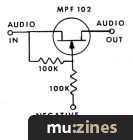
The IC is a transconductance amplifier whose gain is controlled by the current into pin 1. With no signal present transistors Q8 and 9 are off. This allows C15 to charge via R26 almost to the supply rail. This causes a current to flow through Q5 and into the IC via R14 and the resistance set by the Sustain control. This sets the initial gain of the amplifier.

Steps 18-21. Base plate and knobs fitted to complete the unit.
With a signal present Q8 and 9 come on, discharging C15 and causing a voltage drop at the base of Q5 turning it off, the IC now decreases in gain since the control current has stopped. Since the input signal has now reduced C15 again starts to charge and increase the gain of the IC. The circuit therefore keeps the output constant at a level set by the Sustain control. The effect is switched in and out with two FET's Q2 and 3 controlled by a flip-flop toggled by the footswitch.
Operation
Our Compressor worked first time after assembly but should you have any difficulties Roland UK have a 'Plot Line' at their factory which is (Contact Details) — they are always willing to lend a helping ear!
Although Amdek believe they have supplied component values for perfect operation of the unit they do suggest some modifications which can be made. Note that these mods are made at your own risk and may affect guarantee conditions.

Figure 3. Panel description.
Modifications
These modifications alter the Attack and Decay times of the Compressor action.
Mod 1. Resistor R27 determines the discharge rate of C15. If this is increased the 'attack' increases in amplitude giving a very 'punchy' sound. Try values from 0-1k.
Mod 2. Resistor R26 determines the charging rate of C15. When this is decreased the charging rate increases and vice-versa. Try values from 10k to 330k.
Mod 3. For full control over the Compressor action fit a miniature pot in place of each resistor. A 1k in place of R27 and a 220k in series with a 10k resistor in place of R26. The two pots could be fitted below the present controls (with some careful drilling!)
E&MM's special offer price for the Amdek Compressor Kit is £28.00 incl VAT and P&P. Please order as: Amdek CMK-100 kit.
More with this topic
 Equally Tempered Digital to Analog Converter |
 Starting Point (Part 1) |
 To Phase or to Flange - Or To Each His Own |
 Circuit Maker - Digital Equipment Protector |
 How to Calm Hysterics in Op-amps |
 Studio Earthing Techniques - Interconnect (Part 1) |
 DIY Direct Inject Box - A high quality DI box circuit |
 BeeBMIDI (Part 1) |
 Voice Frequency to Voltage Converter |
 Experimenters Circuits - Using The CA3080 |
 Analogue Equipment Design - for Rock 'n' Roll (Part 1) |
 Constructing A Trigger Delay |
Browse by Topic:
Electronics / Build
Publisher: Electronics & Music Maker - Music Maker Publications (UK), Future Publishing.
The current copyright owner/s of this content may differ from the originally published copyright notice.
More details on copyright ownership...

Electronics & Music Maker - Jan 1983
Feature
Ads for Gear in this article:

Help Support The Things You Love
mu:zines is the result of thousands of hours of effort, and will require many thousands more going forward to reach our goals of getting all this content online.
If you value this resource, you can support this project - it really helps!
Donations for June 2026
Issues donated this month: 0
New issues that have been donated or scanned for us this month.
Funds donated this month: £0.00
All donations and support are gratefully appreciated - thank you.
Magazines Needed - Can You Help?
Do you have any of these magazine issues?
If so, and you can donate, lend or scan them to help complete our archive, please get in touch via the Contribute page - thanks!