


Magazine Archive
Home -> Magazines -> Issues -> Articles in this issue -> View
Workbench | |
Lighting Effects on Stage — UpdateArticle from International Musician & Recording World, October 1985 | |
Phil 'Princess DIY' Walsh sheds a little light on stage effects
About a year ago I did a couple of Workbenches on building a simple stage lighting controller. This prompted a batch of letters asking about flashing lights, strobing them, light chasers and rope lights. Thinking about it, it seemed to me that it should be possible to use a basic circuit to provide the chase function and then link this up to a variety of output boards designed to give the particular functions that you want to use with your band. In order to make the system as flexible as possible I finally came up with the following boards:
1. Power Supply board (mains lamps output) — £2.50
2. Power Supply board (LED output) — £5.00
3. Chaser board — £3.00
4. Strobing/Dark Space board (4 channel) — £2.50
5. Mains Lamps Interface board (4 channel, 1KW channel) — £7.00
6. Mains Rope Light Interface board (4 channel) — £4.00
7. LED Interface board — £2.50
To help you with a rough costing I've put an approximate price against each board. Now if you add all that lot up it comes to a horrendous price but luckily you won't need all the boards for any particular project. Table one outlines some of the possible applications and the boards required. (NB lamps are extra — more about that next month)
TABLE 1
| APPLICATION | BOARDS REQUIRED |
|---|---|
| 4 channel, 4kW stage lamp chaser | 1 3 5 |
| 4 channel LED chaser — will chase up to 300 LEDs | 2 3 7 |
| Standard 4 channel rope light controller | 1 3 6 |
| Multi mode LED chaser | 1 3 4 7 |
| Multi mode rope light controller | 1 3 4 6 |
| Multi mode stage lamp chaser/flasher/strober. | 1 3 4 5 |
The Chaser Board
As the only board common to all applications is the chaser, we'll start with that. To make construction as straightforward as possible I've based it on just two integrated circuit chips and a few discrete components. To assist the constructor I've included in the parts list a set of location coordinates for each component — these link up with Figs one and two.
Parts List
1 off 16 din dil socket (E5-L5, E8-L8)
1 off 8 din dil socket (E22-H22, E25-H25)
1 off 10K ohm, ⅛watt resistor (A28-F28)
1 off 22K ohm, ⅛watt resistor (C32-G32)
1 off 470Kohm, linear potentiometer (C34-F34)
1 off 0.033μF polyester capacitor (H26-N26)
1 off 2μF, 16 volt axial electrolytic capacitor (G30-N30)
1 off CMOS 4017B Counter/Divider chip 16 din dil
1 off NE555 timer chip — 8 din dil
1 off Veroboard approx 3½" x 2", 0.1" pitch
+ insulated, stranded wire for hooking up boards

FIG 1. VEROBOARD LAYOUT (Copper Track Side) FOR CHASER BOARD
Construction
1. Turn the Veroboard so that the copper tracks are facing you. Referring to Fig. one, make cuts in the copper tracks at the following locations: E7, F7, G7, H7, I7, J7, K7, L7, E15, H15, I15, C23, E23, F23, G23, & H23 (17 cuts). Cuts can easily be made by twisting a 3mm/⅛" drill into the track until the copper is completely cut away both top and bottom of the hole — a careful visual check that the tracks are completely broken will save problems later.
2. Turn the board over to the non copper side — all components are inserted from this side — and put in and solder the nine wire links (see Fig. two).
3. Fit the two integrated circuit sockets. The sockets should have a chamfer or notch at one end and they should be aligned so that this mark is near track E. Solder the two sockets in place — if they are correctly positioned the copper track breaks should isolate the two rows of pinson each chip.
4. Fit and solder the 10K ohm and 22K ohm resistors.
5. Fit and solder the 0.033μF capacitor.
6. Fit and solder the 2μF capacitor ensuring that the kink in the can (the positive end) is the correct way round (lead connected to G30).
7. Solder two lengths of insulated wire to the pot and back to the board (see Fig. two).
8. Solder four lengths of wire (the output leads) to location F2, G2, H2, K2.
9. Carefully insert the 555 chip into its socket ensuring that the notch or spot is nearest track E, as shown in Fig. two. You may need to squeeze the pins slightly inward to easily fit the ch ip.
10. Touch your hands onto something earthed., e.g. a watertap, and then fit the 4017 chip, correctly aligning the notch. The reason for earthing yourself is that the chip can sometimes be damaged by stray static electricity.
11. Use side cutters to cut all the component leads back to the solder joints. Congratulations, you've just built the chaser board!

FIG 2. VEROBOARD LAYOUT (Component Side) FOR CHASER BOARD
Before you go out to celebrate, a couple of points. Carefully check that there are no whiskers or blobs of solder bridging between adjacent Veroboard tracks — they're easy to miss so look carefully. Secondly check that there are no wire whiskers touching each other where the four output leads go through the component side of the board.
Testing the board
Should you want to test the board at this stage (thoroughly recommended) you will need four additional components:
1 off PP3 battery
1 off PP3 battery clip
1 off red LED
1 off 1Kohm, ⅛ watt resistor
1. Solder the red battery clip lead to location A3 and the black lead to N3.
2. Solder the 1Kohm resistor between locations N12 and Q15 (diagonally)
3. Solder the LED between P25 and Q25 ensuring that the flat on the LED case is nearest the Q track.
4. Solder a length of wire to location P2.
5. Solder a length of wire to location G15.
Testing
1. Make sure the six floating leads are not touching each other or anything else.
2. Connect the battery.
3. Touch the P2 lead to the A16-H16 link, the LED should light. If it doesn't check that the battery has got some life in it, that the LED is the correct way round, that links on lines 16 and 17 are not touching and that the track cut at E15 is truly broken.
4. Touch the ends of the P2 and G15 leads together. The LED should now flash, speeding up as the pot is turned clockwise.
If it does not flash, disconnect the battery and check that all the track breaks are complete, all the components are correctly positioned and the right way round and that there are no solder bridges between tracks.
Having sorted that out the LED should now flash showing that the pulse producing section (lines 15-35) is working.
5. Untwist the two wires and touch P2's lead to each of the four output leads in turn. In each case the LED should flash, but slower than before.
Having done that the board is now fully tested and working. The battery clip can be removed and lead P2 cut off. If required lead G15 can be shortened and soldered to P16 so that the LED gives a permanent, on-board indication of the pulse producer operation.

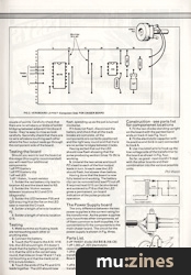
FIG 3. POWER SUPPLY
The Power Supply board
The only difference between the two power supplies is the current rating for the transformer. As the power supplies only have three other components, all of them common to both supplies, it is convenient to fit the components to the main chaser board. The circuit for the power supply is shown in Fig. three.
Parts List.
2 off 1N4001 diode (A4-B4) & (A6-C6)
1 off 1,000μF, 25 V electrolytic capacitor (A15-N15)
1 off 6-0-6 Volt centre tap mains transformer 100mA (mains lamps — Board 1)
OR
1 off 6-0-6 Volt centre tap mains transformer, 1 Amp (LEDs — Board 2)
Construction — see parts list for component locations

FIG 4. TRANSFORMER WIRING AND DIODE FIXING DETAILS
1. Fit the two diodes standing upright on the board with the painted band ends on track A (see Fig. four).
2. Fit the electrolytic capacitor with its positive end (kink in can) connected to track A.
3. Use insulated wire to hook up the low voltage side of the transformer to the board as shown in Fig. four.
So far, so good — next month I'll deal with the other boards and their combination into the various possible units.
More from these topics
 Studio Earthing Techniques - Interconnect (Part 1) |
 Adding Fine Tuning To Standard Controls |
 Dual Voltage-Controlled LFO |
 Multi-waveform LFO |
 Projected Developments |
 Phantom Power Module |
 The Ultimate Blinky Light - LED Wall Art - Visual Environment Machine |
 Technically Speaking |
 How to Calm Hysterics in Op-amps |
 Practically MIDI (Part 1) |
 Build A Hum Loop Isolator |
 Magic Buttons - Touch Switch Theory |
Browse by Topic:
Electronics / Build
Lighting
Publisher: International Musician & Recording World - Cover Publications Ltd, Northern & Shell Ltd.
The current copyright owner/s of this content may differ from the originally published copyright notice.
More details on copyright ownership...

International Musician - Oct 1985
Donated by: Mike Gorman, Neill Jongman
Scanned by: Mike Gorman
Feature by Phil Walsh
Previous article in this issue:
Next article in this issue:
Help Support The Things You Love
mu:zines is the result of thousands of hours of effort, and will require many thousands more going forward to reach our goals of getting all this content online.
If you value this resource, you can support this project - it really helps!
Donations for May 2026
Issues donated this month: 0
New issues that have been donated or scanned for us this month.
Funds donated this month: £0.00
All donations and support are gratefully appreciated - thank you.
Magazines Needed - Can You Help?
Do you have any of these magazine issues?
If so, and you can donate, lend or scan them to help complete our archive, please get in touch via the Contribute page - thanks!