


Magazine Archive
Home -> Magazines -> Issues -> Articles in this issue -> View
Electronics for Music | |
Oscillators And WaveformsArticle from Electronics & Music Maker, September 1983 | |

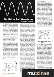
Figure 1. Sine Waveform.
Looking back through past issues of 'Electronics And Music Maker' it is not difficult to find a number of projects which use at least one oscillator, and a brief examination of a few circuits reveals that the oscillator circuits used vary considerably from one project to another. The reason for this diversity of oscillator configurations is merely that the requirements differ greatly, with one project perhaps requiring a squarewave clock signal at a high frequency of a few hundred kilohertz, and another project needing a sub-audio oscillator having a triangular waveform to operate a VCA, VCF or VCO.
In this article, we will consider a few useful oscillator circuits which provide most waveforms that the electro-musician is likely to need. One or two Voltage Controlled Oscillator circuits will be included.
Sinewave Generator
The oscillograph of Figure 1 shows a sinewave, this being an important waveform since it is produced by an oscillator which provides a fundamental with no harmonics or other frequencies. This gives an audio sinewave signal a very distinctive sound which is easily distinguished from any other waveform.
Although a sinewave is in away the most basic of waveforms, it is actually quite difficult to generate a very high quality signal of this type. Probably the most common type of sinewave generator is the Wien Bridge type, and a circuit of this type is shown in Figure 2. Frequency selective positive feedback is provided over IC1 by C2, C3, R3 and R4, the circuit oscillating at the frequency where there is maximum feedback, provided the voltage gain of IC1 at least compensates for the losses through the Wien feedback network.
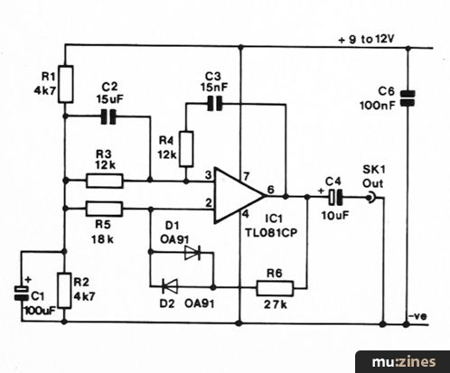
Figure 2. Sinewave generator circuit.
If the voltage gain of IC1 is accurately stabilised at a level which is just sufficient to produce oscillation, a good quality sinewave will be produced at the output. If the voltage gain is only marginally lower the circuit will simply fail to oscillate at all. Slightly excessive gain is sufficient to produce strong oscillation that results in the output being clipped and badly distorted. In order to obtain good results it is necessary to have some form of automatic gain control to maintain the gain of the circuit at precisely the correct level.
Special thermistors such as the RA53 type are often used to give this stabilisation, and circuits using these are capable of extremely good results. However, thermistor stabilisation has two major drawbacks which are the high cost of suitable thermistors (about £5.00 each) and a drop in performance at very low frequencies. The circuit of Figure 2 uses a simple and inexpensive alternative which gives a slightly less pure output than that obtained using thermistor stabilisation, but the distortion is still only around one or two per cent which is more than adequate for most purposes. The circuit also functions well at very low frequencies.
The closed loop voltage gain of IC1 is controlled by the negative feedback network formed by R5, R6, D1 and D2. With only a small output voltage D1 and D2 have a relatively high resistance so that the circuit has sufficient gain to oscillate reasonably strongly, but at higher output voltages their resistance is much lower and the voltage gain of IC1 is reduced. This prevents the circuit from oscillating so strongly that the output is clipped and seriously distorted, although the action of D1 and D2 rounds the waveform peaks and produces the small amount of distortion mentioned earlier.
The specified values for the components in the Wien network give oscillation at approximately 1kHz, but changing the value of C2 and C3 gives an inversely proportional change in operating frequency, as do changes in the value of R3 and R4. This enables the circuit to operate at any frequency from about 0.1 Hz to a few hundred kilohertz. By using a dual gang potentiometer plus fixed value series resistors for R3 and R4 the operating frequency can be made variable. The output level is about one volt peak-to-peak.

Figure 3. Square and Triangle waveform generator.
Square/Triangle Wave Oscillator
Figure 3 shows the circuit diagram of a very useful oscillator which gives both Triangular and Squarewave outputs, Figure 4 shows the output waveforms of this circuit.
A low or medium frequency squarewave signal sounds very harsh when compared to a sinewave signal, this being due to the strong harmonic content. A high frequency squarewave does not sound different to a sinewave of the same frequency simply because the harmonics will be above the upper limit of human hearing. A square-wave only has odd harmonics (three times the fundamental frequency, five times the fundamental frequency, seven times the fundamental frequency, and so on), with the relative strengths of of the harmonics reducing as they become further removed from the fundamental. In fact the third harmonic is only one third of the amplitude of the fundamental, the fifth harmonic is just a fifth as strong as the fundamental etc.

Figure 4. Output waveforms from Square/Triangle generator.
A triangular waveform has a weak harmonic content, although the harmonics are strong enough to be clearly heard on a low frequency triangular signal. It is the third and fifth harmonics that are present, but only at half the amplitude as the same harmonics in an equivalent squarewave signal. Due to the low harmonic content of triangular signals they are often used as the low frequency control signals in effects units such as Tremolo, Phaser, Flanger and soon, but sinewave generators should be used in applications of this type. Incidentally, the analysis of the frequency components of a waveform is called 'Fourier Analysis'.
The way in which the circuit of Figure 3 operates is quite straight forward with IC1a being used as an integrator and IC1b acting as a Schmitt trigger. Initially the output of IC1b is high and C3 charges via R3, but IC1a maintains its two inputs at the same potential by a negative feedback action, and this results in the output of IC1a going negative at a fixed rate. When this output voltage goes below about one quarter of the supply voltage the potential divider action across R4 and R5 takes the non-inverting input of IC1b below the bias voltage fed to the inverting input so that IC1b's output triggers to the low state. A reverse circuit action then occurs with C3 discharging through R3 and the output of IC1a steadily rising in voltage until it reaches about three quarters of the supply potential. The circuit then triggers back to its original state, and this whole process repeats indefinitely.
Thus a triangular waveform with a peak-to-peak amplitude of about half the supply voltage is generated at the output of IC1a, and a squarewave output with a peak-to-peak amplitude of about three volts less than the supply voltage is produced at the output of IC1b. Looking at Figure 4 it will be apparent that the output waveforms do not have a perfect one-to-one mark-space ratio, and this is caused by IC1b having a peak negative output voltage which is about 2 volts above the negative supply rail, and a peak positive voltage which is about one volt less than the positive supply potential. It is possible to compensate for this lack of symmetry, if necessary, by using a 10k preset potentiometer in place of R1 and R2, and adjusting this for a one-to-one mark-space ratio.
The specified values for R3 and C3 produce a fundamental output frequency of approximately 1kHz, but as with the previous circuit these can be changed in value to give any operating frequency from about 0.1 Hertz to a few hundred kilohertz.

Figure 5. Voltage controlled Triangle wave generator.
Triangular VCO
Figure 5 shows the circuit diagram of a simple but useful VCO which gives a reasonable triangular output waveform, and this circuit could be employed in applications such as the generation of falling pitch drum sounds. IC1 is a transconductance operational amplifier which is used to charge and discharge C2 at a linear rate and generate a triangular waveform. The control voltage determines the charge and discharge current and therefore the operating frequency of the circuit. R3 and R4 set the peak-to-peak output voltage of the circuit, and this is approximately 5 volts with the values given in Figure 5. IC2 is merely used as a buffer stage which gives the circuit a low output impedance.
The frequency range of the circuit is very wide with an output frequency of just a few Hertz with the control voltage at a low figure of about 0.5 volts, rising to an operating frequency of about 7kHz with a 9 volt control voltage. The frequency span of the circuit can be shifted up or down by altering the value of C2, with changes in value giving an inversely proportional shift in frequency range. Note that C2 (and the timing capacitors in the other two circuits described in this article) cannot be polarised types such as electrolytic or tantalum bead capacitors.
More with this topic
 Workbench |
 Short Circuit - Time Machine Revisited |
 Electronic Drum Sequencer - Software for BBC Micro |
 An Ultra VCO From The 4720 |
 The Spectrum Synthesiser (Part 1) |
 Magic Buttons - Touch Switch Theory |
 Chip Parade (Part 1) |
 Workbench - Sounding Out |
 Universal Bass Pedal Synth |
 On the Level |
 How to Calm Hysterics in Op-amps |
 Digital Signal Processing (Part 1) |
Browse by Topic:
Electronics / Build
Publisher: Electronics & Music Maker - Music Maker Publications (UK), Future Publishing.
The current copyright owner/s of this content may differ from the originally published copyright notice.
More details on copyright ownership...

Electronics & Music Maker - Sep 1983
Feature by Robert Penfold
Previous article in this issue:
Next article in this issue:
Help Support The Things You Love
mu:zines is the result of thousands of hours of effort, and will require many thousands more going forward to reach our goals of getting all this content online.
If you value this resource, you can support this project - it really helps!
Donations for June 2026
Issues donated this month: 0
New issues that have been donated or scanned for us this month.
Funds donated this month: £0.00
All donations and support are gratefully appreciated - thank you.
Magazines Needed - Can You Help?
Do you have any of these magazine issues?
If so, and you can donate, lend or scan them to help complete our archive, please get in touch via the Contribute page - thanks!