


Magazine Archive
Home -> Magazines -> Issues -> Articles in this issue -> View
The Syndrom (Part 1) | |
How it WorksArticle from Electronics & Music Maker, April 1984 | |
Part one of a series on designing and building a digital percussion sampling device.
Sampled drums have become so much the norm these days — a syndrom (e) of modern music, you might say — we felt it was about time we devoted an E&MM project to this area of musical technology. Because this technology is relatively new, a lot of it is priced well beyond the reach of the average modern musician, yet the Syndrom can be built for only the fraction of the cost of ready-built units. Design and presentation by Ken Pykett, Clive Buxton, and David Ellis.
Rather than presenting an entire digital drum machine project, where a dedicated processor is used to goad digitised sounds into action, we've elected to go for a more modular approach consisting of individual drum boards with pre-programmed sound EPROMs. And since each board will cost just £10 to put together, plus £5 or £6 for a pre-programmed 2716 or 2732 sound EPROM, there's very little financial outlay involved in starting the project.
In fact, the board is just about as basic as you can get, including as it does a clock, a set of counters, some triggering circuitry, the all-important EPROM, and a DAC and buffer to turn all the theory into acoustic reality. Definitely a no-frills or fancies approach!
We did think about adding a further counter to increase the address range to cover the use of a 2764 (8K) EPROM, but decided against this because of pin connection differences between this and 2716/32 EPROMs, and the fact that cymbal-type sounds really need considerably more than 8K to do them justice. We may well produce a further design specifically for longer sounds, however, in the not-too-distant future.
The point to bear in mind about the Syndrom is that it can be used in a host of different ways, and over the next few months we'll be looking at some of the following possibilities:
1 A means of adding on new percussion sounds to any drum machine.
2 A micro-interfaceable drum module.
3 A monophonic sampled voice for keyboard control.
4 A sound-effect foot pedal.
5 A dynamic live drum sound played from pads.
6 A means of finding out what your monitor ROM actually sounds like(!)
Some of these applications will require modifications (for CV control, for instance) and retro-fits (to enable dynamic pad playing) to the basic unit, and we'll be following these up as and when necessary.

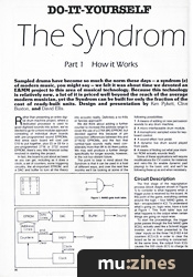
Figure 2. Syndrom block diagram.
Circuit Description

Figure 1. NAND-gate truth table.
The first stage of the regurgitation process (block diagram shown in Figure 2) to consider is what happens when a trigger pulse is received by the board. At this point of the game, everything centres around the logic - four NAND gates, in fact - encapsulated in IC2. To understand what's going on, logic-wise, have a look at Figure 1. This 'truth table' lays out what happens to the output when certain things are going on input-wise.
To start the proceedings, the trigger pulse passes through the first NAND gate (IC2c), actually used like a Schmitt trigger inverter, and is then presented to the 'clear' inputs on the three 74LS163 4-bit counters (IC3, 4, 5) in order to clear the board as far as counting is concerned. At the same time, the output from IC2c causes the 555 clock (IC1) to charge its timing capacitor (C1).
Then, providing the trigger pulse is greater than the charge period (approximately 150us), the clear condition will be implemented by the rising clock pulse. If it isn't long enough, the pulse will be regarded as noise and won't start the count. Once the counters are cleared, the appropriate Q output or terminal count (depending on which type of EPROM is being used) from the last counter will fall, and the clock enable input on the 555 will be held whilst the clock is putting the counters through their cycling routine. If the trigger input remains high, the counters will cycle continuously, thereby giving a roll effect to the sampled sound.
Alternatively, the method of triggering can be altered so that the count is initiated on the falling edge of a square wave by short-circuiting C2. The basic circuit therefore allows triggering from both positive-and negative-going trigger sources, and is also suitable for direct TTL-triggering from a micro. At the same time, if the trigger pulse is repeated before the entire sample has been used, the trigger signal is differentiated by C2, R5, and D1, with the result that the counters are cleared and the sampling output re-started, which is necessary if you're after the effect of a drum undergoing rapid paradiddles.
Sounds are supplied pre-digitised in 2716 (2K) or 2732 (4K) EPROMs. In the case of the former, only 11 address lines (A0-A10) are involved and Q3 of the third counter (IC5) goes to reset the triggering circuitry. If a 2732 EPROM is used, the Q3 line of IC5 goes to All (pin 21), and the terminal count output of IC5 goes to IC2a. To simplify these alternative matters, it's easiest if you add a switch (SW1) as shown in the circuit diagram, but, if only one sort of EPROM is likely to be used, the switch can be replaced with links. Note, however, that using a switch also allows the contents of a 2732 to be played only as far as the first 2K, ie. halving the sample duration, a facility that may be useful in certain situations - especially when playing samples at a lower than normal pitch.
The EPROM is clocked by using binary synchronous counters configured to count up to a desired maximum according to whatever EPROMs are currently in vogue. The original circuit used a ZN425E DAC as the digital-to-analogue converter because of its blissfully untroublesome power requirements (single-rail, 4.5 to 5.5 volts). However, even though the final choice of the DAC0800 makes life complicated by requiring bi-polar supplies (though this is easily achieved for a single board with a couple of PP3s), the output swing is rated at up to 20volts peak-to-peak, which makes for an extremely dynamic sound, and, what's more, the chip is less than half the price of the ZN425. R2 is provided to allow the user to vary the clock rate (and therefore the sample length/pitch of the digitised sound) over a range of widely variable usefulness.

Figure 3. Syndrom circuit diagram.
(Click image for higher resolution version)
Errata: The circuit diagram for the Syndrom contained two wrong voltage values. The voltages on IC7, pins 3 and 13 should have been -9V and +9V respectively.
The other point of errata is that a couple of blobs got lost in the circuit diagram wash, and these should be at the junction of C3, C4, -9V, and pin 3 of IC7, at the junction of C5, +7V, and pin 13, and at the junction of the common connection of IC9 with ground.
One circuit fact that needs a word of explanation is the present lack of any low-pass output filter. To be honest, trial and error has given us the impression that with short, sharp sounds like those from the percussive stable, the ear's so stunned by their dynamism that it couldn't give a hoot about what else is going on around the D/A converted signal in the way of clocks, grunge, and the like! On second thoughts, that sounds terribly unscientific, so we'd better say that filters will be added on later (together with dynamic control circuitry) as a retro-fit...
Next month, we'll have the details of the EPROMs available for the Syndrom and how you can go about getting them. Also, a PCB should be available by then to make constructional life a little easier.
Series - "The Syndrom"

More with this topic
 Digisound Voice Card (Part 1) |
 Short Circuit - Time Machine Revisited |
 Destiny Modular Mixer - Input Module (Part 1) |
 Reverb Modification |
 Interfacing External Signals with the Gnome Micro-Synthesizer - Guitar/Gnome Interface |
 The Ultimate Blinky Light - LED Wall Art - Visual Environment Machine |
 BeeBMIDI (Part 1) |
 Test Tone Oscillator |
 The Layman's Guide to Digital Logic Gates - (in one easy lesson) |
 Trigger Converter for the Yamaha SPX-90 |
 A Low Cost, Special Purpose AR Generator |
 Confessions - ...of an English kit builder. |
Browse by Topic:
Electronics / Build
Publisher: Electronics & Music Maker - Music Maker Publications (UK), Future Publishing.
The current copyright owner/s of this content may differ from the originally published copyright notice.
More details on copyright ownership...

Electronics & Music Maker - Apr 1984
Feature by Ken Pykett, Clive Buxton, David Ellis
Previous article in this issue:
Next article in this issue:
Help Support The Things You Love
mu:zines is the result of thousands of hours of effort, and will require many thousands more going forward to reach our goals of getting all this content online.
If you value this resource, you can support this project - it really helps!
Donations for July 2026
Issues donated this month: 0
New issues that have been donated or scanned for us this month.
Funds donated this month: £0.00
All donations and support are gratefully appreciated - thank you.
Magazines Needed - Can You Help?
Do you have any of these magazine issues?
If so, and you can donate, lend or scan them to help complete our archive, please get in touch via the Contribute page - thanks!