


Magazine Archive
Home -> Magazines -> Issues -> Articles in this issue -> View
4-Channel Stereo Mixer | |
Article from Electronic Soundmaker & Computer Music, February 1984 | |
4 Into 2 does go!
A stereo mixer with parametric equalisation on each channel. Design by Mark Stuart

Audio mixers may appear in many forms but all share the same purpose — that of combining multiple signal sources into a lesser number of signal outputs.
The circuit presented here takes four input channels and allows them to be mixed in any proportions into two output channels. Each input channel has its own parametric equalisation stage which allows a response peak or dip of variable depth to be positioned anywhere in the audio frequency band. Independent effects controls on each channel allow any mix of input signals to be fed to an external monitor amplifier or electronic effects unit. The return signal from an effects unit can be remixed into the two output channels in any proportions.
A 'pan pot' on each channel enhances the mixer performance when used to provide a stereo output. 'Panning' the signal sweeps it smoothly from one channel to the other using a single control. Each output has a master level control; the mixer is designed to be used at 'line' levels of approximately one volt peak. The input impedance is 50k ohms. The output can drive loads down to 10k ohms; the overall gain through the mixer is one.

Fig 1. Circuit of one channel of the mixer. Note that all the outputs are shown.
(Click image for higher resolution version)
Construction

Fig 2. Overlay for the identical input boards.
(Click image for higher resolution version)
A modular approach, using individual printed circuit boards for each input channel, has been adopted. This method allows the number of input channels to be varied to suit particular applications. A second printed circuit board combines both output channels and the effects in/out amplifier stages. On both boards the potentiometers are mounted on the component side, with their spindles passing through to the copper track side. A sufficient length of mounting bush remains on each control to be passed through a metal facia panel.
Prior to assembly the boards can be used as templates to mark out the facia panel for the drilling of the 3/8" mounting holes. Ensure that the panel holes are cleared of burrs which could cause short circuits on the boards. A second set of holes, to accommodate the jack sockets, should be drilled in the rear of the case. A case made from 18swg aluminium is recommended for easy drilling.

Fig. 3. Overlay for the master control board.
(Click image for higher resolution version)
Once the metalwork is complete the printed circuit boards should be assembled. Refer to Figs 2 and 3, and first fit the wire links, resistors and IC sockets. Fit single sided PCB connecting pins to the nine wiring points on each channel board and the 16 points on the output board. The potentiometers should be fitted next; refer to Fig 4 and start with the single gang type. Be careful when bending the tags forward — if possible use a pair of pointed pliers. Dual controls VR2 and VR4 must be wired as shown in Fig 4, before mounting. Take care to link the tags exactly as shown. Note that there are only three connections to the board from VR3 and four from VR4. Finally fit the capacitors, ensuring that the electrolytics are the correct way round.
Check each board thoroughly after assembly for dry joints, solder bridges and incorrect components. A little time now can save hours later.
Use screened wire to connect the channel inputs & the signal outputs to their respective jack sockets.
The effects in and out pins (labelled EFFIN & EFFOUT) on the output board should be wired with screened cable. The screen MUST NOT be connected at the circuit board end. At the socket end the screens should be connected to the sleeve terminals as usual. An additional connection from these sleeve terminals on the output sockets must be made to provide the signal ground connection.

Fig. 4. Potentiometer wiring and connections.
Interconnection between the circuit boards is achieved simply by linking all the terminal pins with the same letter. Thin stranded insulated connecting wire should used, wrapped around each terminal before soldering. This operation is simplified if the boards are first mounted to the facia panel.
When the wiring is complete fit the battery clips to SW1 as shown in Fig 3, and insert the ICs. Connect two sets of four 1.5 volt cells. The unit is now ready for testing.
Testing

The Stereo Mixer PCB foil pattern
(Click image for higher resolution version)
Testing is best carried out by connecting each channel in turn to an amplifier (turned well down). Connect a signal source to one input and check the behaviour of the controls.
The parametric equaliser section is best tested with a source of fairly broad band signals. When set to maximum peak, sweeping the frequency control will produce a wah wah effect. When set to maximum dip the effect appears to be more subtle. The function of the other controls should be self explanatory.
Fault Finding
It should be fairly straightforward to identify any faults. A fault on a single channel is likely to be on the associated input channel board. A fault appearing on all channels is probably on the output board. The most likely faults are dry joints, crossed wires or incorrect components.
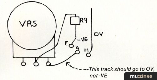
[Errata, Lead Lines Aug/Sep 84 issue: Pot VR5 on the input boards should go to 0V, not -VE.]
Parts List
| Resistors | |
| R1,3,4,9,10,11 | 47k |
| R2 | 8k2 |
| R5,6 | 2k2 |
| R7 | 10k |
| R8 | 2M2 |
Capacitors | |
| C1 | 100n C280 |
| C2,3 | 22n C280 |
| C4 | 10u 25V radial electrolytic |
| C5 | 10u 16Vradial electrolytic |
| IC1 | TL072CP |
Potentiometers — all 20mm dia. PCB mounting | |
| RV1,5 | 47k Log |
| RV2 | 100k Lin |
| RV3,RV4 | 100k Lin Dual |
| PCB, knobs etc. | |
| Above Parts for 1 input Channel (4 sets for 4 Input mixer) | |
Resistors — all ¼W 5% carbon film | |
| R12,13,14,15, 16,17,18 | 47k |
Potentiometers — 20mm dia. PCB mounting | |
| RV6,RV7 | 10k Log |
| RV9 | 47k Log |
| RV8 | 100k Lin |
Capacitors | |
| C6,7,8,9 | 100n C280 |
| C10,C11 | 100u 10V Radial Electrolytic |
| IC2, IC3 | TL072 |
Miscellaneous | |
| Switch SW1 — DPST Rotary, Case — aluminium approx 210x150x50, Jack sockets, SK1 — Mono break, 1 per input channel, SK2,3,5 — Mono, SK4 — Mono Break, Battery clips PP3 type — 2 off, Battery holders 4 x HP11 type — 2 off, knobs, wire, PCBs etc. | |
More with this topic
 Workbench - Signal Processors - Frequency Response Modification |
 The Matinee Organ (Part 1) |
 Circuit Maker - Digital Equipment Protector |
 Workbench - Impedance. What is it?! |
 The Miniblo |
 Powertran MCS1 - Playing with Time (Part 1) |
 Short Circuit - Time Machine Revisited |
 |
The Transpozer (Part 1) |
 Using Microprocessors (Part 1) |
Starting Point (Part 1) |
 Lab Notes: In Pursuit of the Wild QuASH |
Browse by Topic:
Electronics / Build
Publisher: Electronic Soundmaker & Computer Music - Cover Publications Ltd, Northern & Shell Ltd.
The current copyright owner/s of this content may differ from the originally published copyright notice.
More details on copyright ownership...

Electronic Soundmaker - Feb 1984
Donated by: Ian Sanderson
Feature by Mark Stuart
Help Support The Things You Love
mu:zines is the result of thousands of hours of effort, and will require many thousands more going forward to reach our goals of getting all this content online.
If you value this resource, you can support this project - it really helps!
Donations for June 2026
Issues donated this month: 0
New issues that have been donated or scanned for us this month.
Funds donated this month: £0.00
All donations and support are gratefully appreciated - thank you.
Magazines Needed - Can You Help?
Do you have any of these magazine issues?
If so, and you can donate, lend or scan them to help complete our archive, please get in touch via the Contribute page - thanks!