


Magazine Archive
Home -> Magazines -> Issues -> Articles in this issue -> View
Eliminating Patch Cords Without Eliminating Capability | |
A Practical ApproachArticle from Polyphony, July 1977 | |
In working with the PAIA synthesizer, I have found that the main drawback of studio synthesizers is still present — PATCH CORDS! Those little demons are either just a little too short, or three times too long for the patch.
Totally prepatched is not the answer, either. Great on the road, but get them in a studio and everything sounds the same.
The ultimate would be a combination of both. Certain patches quickly available but easily modified and/or removed for more progressive work.
Unfortunately, only one such synthesizer with these capabilities exists. Several have made some attempts to interface a unit with the outside world, but the ARP 2600 still reigns supreme.
I've played and worked, laughed and cursed, created and destroyed, and some ideas are coming to a head. I would like to share them.
My first system was a PAIA 2720/A. Quickly there followed additions and wing cabinets. One of my first concerns was quickly switching audio sources into and out of processing modules. Plugging patch cords from sawtooth to square to triangle took too long, and plugging from one output to another caused pops in the amplifier.
The circuit below was the first that came to mind. Simple construction with audio jacks and rotary switch in a bake-lite box, all parts readily available.

Note that this is a six-position switch. This would accommodate square, sawtooth, triangle, sine, modulated pulse, and noise. This switch, being a passive unit, is bi-directional; that is, inputs could be outputs and vice-versa. I built two such switches, and they serve me very well.
In any system, it seems that there are more control cords than audio. I guess this is as it should be. In any case, more need arises for switching controls than audio. The problem here is that in many cases controls may have to be changed (like the above audio example), modified, or shut off completely. Each change can be effected with the output level controls on many of the modules, but at the expense of accurately repeating the patch. The following sketch is the germ idea.

A simple SPDT switch and three pin jacks are all that's required. I suggest a toggle type switch. They give you direct visual indication of which input is selected (but so do the square slide type) and you don't have to drill square holes.
Digressing for a moment, a strong point should be made about the visual feedback. It is extremely important that all switch positions be accurately labeled. One should be able to simply look at your switches and tell what function they serve. In the previous examples it is not so important to know which jack connects to what function, but which switch position connects to which jack. The particular input to any one jack may change from patch to patch, but a given switch position should produce a given response in any one patch.
Back to control switching: The SPDT set up works nice for two different inputs, but what if you want to simply change one input? A good example would be a different amount of filter sweep from the same envelope generator. Obviously this can be done with the variable output jack, but each change reduces the possibility of exactly repeating the others. A slight change here takes care of the problem:

Patching the variable output into (1) and the fixed output into (2) allows for two totally variable outputs which are instantly and exactly repeatable.
But why not go one better:

This would allow the same effect as the first, but with even more versatility.
One more variation, now. I have one of these, but I haven't found much use for it. Maybe you can.

One important thing to note. Each of these circuits require a ground reference. I built two of the audio switches and two of the control switches in the same box. I always use shielded cable, so all of the grounds (including audio) can be tied in through the shield. If you build the control switches alone, it will be necessary to make provisions for a separate ground input jack.
The circuits shown to this point did solve one of the problems concerned with here: quick and accurate selection of a patch. However, the other problem, length and number of patch cords, has been multiplied. To select one of two controls now requires three cords instead of one, and to select one of four oscillator outputs requires five cords.
In my search for innovative new sounds, I found that I required more oscillators and filters, and that all must track the same source, the keyboard mostly. I purchased three 2720-2A oscillators and one 4730 filter. Any one can see how many patch cords this would require! There are a couple of hidden problems, though.
How do you construct a chord with the three oscillators and then process it with the filter? First off, the filter and all three oscillators must track. A manual transposer handles this well. Now you need a mixer between the oscillators and the filter. Before you are done you have about $175 tied up in a "voice module". But take heart!
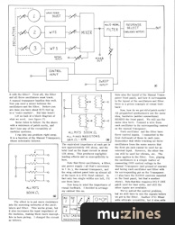
Let us look at a block diagram of what we need, (see figure F)

Some rules to follow: Do the above with a minimum of patch cords, and don't lose any of the versatility of modular systems.
I ran into one problem right away. It is a function of the Manual Transposer, whose schematic follows:

The effect is to put more resistance into the summing networks of the oscillators and filter. This works great, but it also increases the input impedance of the modules, making them more susceptible to hum pickup. I changed the circuit as follows:

The equivalent impedance of each pot is now approximately 5OK ohms, and the total load on the input circuit is about 12K ohms. This produces negligible loading effects and no susceptibility to hum.
Note that three oscillators, a filter, one power supply (all that's necessary is ±9v.), the manual transposer, and the wing cabinet panel take up almost all of the room in a 4761 Road cabinet. In fact only two single widths are left, I'll use them later.
Now keep in mind the importance of visual feedback. I decided to arrange my cabinet like so:

Note also the layout' of the Manual Transposer front panel, and how it corresponds to the layout of the oscillators and filter. Here is a prime example of visual feedback!
Now, how do we get rid of patch cords? All prepatched synthesizers use the same idea, hardwire (solder connections) BEHIND the front panel. We will use the same idea here. Connect a wire from each oscillator to its corresponding control on the manual transposer.
Each oscillator and the filter have three control inputs. I connected to the first (leftmost) of these in each case. Remember that while tracking all three oscillators from the same source that the first pin jack cannot be used for an external input. However, the other two can still be used for vibrato, etc. The same applies to the filter. Now, playing the oscillators is a simple matter of connecting ONE control voltage to the Manual Transposer (and ground of course) and tuning each oscillator and filter with its corresponding pot on the Transposer. (I also have the RANGE controls mounted on the front panel, but that's another story). Note that this requires ONLY ONE patch cord for four units, and still the other inputs are available.
We've solved the control problem, but we still have to mix the signals before we get to the filter. Another 4711 Mixer adds ultimate versatility, but it also adds more cost for features we don't need (like panning and stereo). The circuit shown in figure (k) is no surprise, and serves the purpose very well.

Each oscillator has a separate level control. Maximum volume is unity gain for the oscillators and 2 for the extra (or wild) input. The wild input is for adding another oscillator, noise, or cascading filters. The extra gain makes up for some signal loss. Be careful that the total input does not exceed that allowable for the filter, or distortion will result.
Also included is a filter bypass output. This simply parallels the filter so that the mixer output may be processed by another filter in parallel, or the included filter may be bypassed completely. This unit may be breadboarded and suspended from the back of the panel. Here is a front panel layout. This mixer will take up one section of the blank space in the 4761 cabinet.

We still have one problem. How do we select which waveform goes into the mixer? This will require some modification to the oscillator panels. A simple Or type of switching is used, and constructed from two SPDT switches. Each oscillator will require one such switching circuit.

I mounted these switches just below the Pulse Width control knob, and included appropriate labels. One switch selects either the "hard" or "soft" waveforms. When wiring these switches, wire directly to the proper point on the output jacks of the oscillators. Here is versatility again, since the oscillators maybe mixed, yet each output is separately available.
The only thing left is to quickly select one of the filter outputs. This is easily done with a rotary switch like our first audio switch. However, the filter has a hidden notch output that we can use. Another small mixer is needed here.

This circuit produces an output that is continuously variable from lowpass through notch to high pass. I must admit I have found this tuning ability to be of little use, so if it is not desired simply remove the 500K pot and replace the two 22K resistors in each leg with one 47K resistor.
Now the filter outputs maybe selected like this:

Again, wire directly from the output jacks so that each output still remains individually accessible. Build this unit into the remaining single blank panel space in the 4761 cabinet.
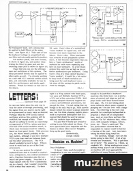
We still have one problem of "preventative medicine". We must take care that we do not have two inputs to the filter. If the mixer output is wired directly to the filter input jack (like it should be) provisions must be made that something cannot be plugged in the jack at the same time. We could remove the jack, but this would decrease the usefulness of the module. Therefore, we must change the input jack.
A closed circuit type should be used to replace the filter input jack. It is drawn like so:

Its action is such that if nothing is inserted, terminal 2 is connected to terminal 3. Terminal 1 is ground. In use, terminal 2 will make no contact with anything inserted in the jack, while terminal 3 will contact the tip of the plug. We can use this as shown below.

Now, with nothing plugged in, the filter is connected to the mixer (we just saved another patch cord), but with a plug inserted the mixer is disconnected and the plug becomes the input.
With assembly completed, let's see what we have. (1) Control voltage input requires one cord into the unit. (2) Audio output from filter requires one cord. (3) Ground requires one cord — WHICH MAY BE ELIMINATED WITH SHIELDED AUDIO CABLE! This means that this unit requires only THREE patch cords to run all units. A fourth will be necessary in order to sweep the filter, and none will need to be disconnected, eliminating pops, thumps, and time-consuming fumbles. In addition, ALL INPUTS AND OUTPUTS ARE INDIVIDUALLY ACCESSIBLE.
I think that a few remaining notes on the uses of this unit may be in order. One of the most useful features of this is the wild input for the mixer. Obviously, another oscillator could be added for a bigger chord, or noise mixed in. But what about a 24 db/octave filter?
For this effect, two 4730 filters must be SERIES CONNECTED. Apply an audio signal to the first filter (not in the prepatched unit). Take the low pass output and route it to the wild input of the mixer. Adjust all oscillators to minimum and the wild input to suit.
Now, run a control voltage into the Transposer. Using the jack on the transposer that corresponds to the filter, take the control voltage to the first filter. Now, carefully tune each filter to the same cut-off frequency. This is best accomplished by using a little Q on each filter (about half way around) and tune for maximum resonance. Note that this also can produce a very high Q filter, so take care that no distortion results as the Q is advanced. Now, the cut-off of the filter set up may be controlled by the transposer knob, and a sweep may be applied to both filters at the same time, (see figure (t).) Take note of how the keyboard voltage is prepatched into one filter and externally patched to another.

Yet another patch, a la Isao Tomita, is shown in figure (u), and another illustrating the filter by-pass jack and the switching input jack is shown in figure (v).


I hope that you can see the ultimate ease and usefulness of this system. The ideas presented herein may be applied to other units as well. I'm already working on a unit with ALL controls switch selectable, yet externally available for use in both live performance and studio applications. Watch for details on this unit in the future.
Ed. note: Gary's idea of a normalized "voice module" is a good one, and will become even more important in the future. Here's why. When your goals turn towards a true polyphonic synthesizer, it will become imperative that you have a "basic synthesizer" worth of modules for each voice capability you have on your keyboard. In a full blown system this could run as high as ten or twelve synthesizers per keyboard. Using Gary's idea of a wing cabinet housing a "voice module"s it would be a lot easier to keep track of which modules are being used for each keyboard voice — let alone all the savings in patch cords. Food for thought.
More from these topics
 Adding an Independent Tracking Output to the 4780 Sequencer |
 Multi-waveform LFO |
 Fret Work - Could You Be A Guitar Tech? |
 Trigger Converter for the Yamaha SPX-90 |
 When Is A Switch |
 Workbench - Remote Control System |
 Bionic Trumpet |
 Understanding Electronics - How To Make Music Projects |
 An Emulator for £10 |
 Improve Your Instrument - Really, really serious and totally brilliant ways to... |
 Build A Hum Loop Isolator |
 Hot Wiring your Guitar |
Browse by Topic:
Electronics / Build
Maintenance / Repair / Modification
Publisher: Polyphony - Polyphony Publishing Company
The current copyright owner/s of this content may differ from the originally published copyright notice.
More details on copyright ownership...

Polyphony - Jul 1977
Donated & scanned by: Mike Gorman
Feature by Gary Bannister
Help Support The Things You Love
mu:zines is the result of thousands of hours of effort, and will require many thousands more going forward to reach our goals of getting all this content online.
If you value this resource, you can support this project - it really helps!
Donations for July 2026
Issues donated this month: 0
New issues that have been donated or scanned for us this month.
Funds donated this month: £0.00
All donations and support are gratefully appreciated - thank you.
Magazines Needed - Can You Help?
Do you have any of these magazine issues?
If so, and you can donate, lend or scan them to help complete our archive, please get in touch via the Contribute page - thanks!