Magazine Archive
Home -> Magazines -> Issues -> Articles in this issue -> View
Lab Notes: Potpourri & The Apple Connection | |
Article from Polyphony, November 1977 | |
At last, our computer is in production.
It took longer than most because it's a more complex thing than most (The amazing PAIA Do-All machine - you may substitute any manufacturer's name for ours). The Assembly And Using manual, for instance, is 64 pages. The programming manual (supplied by MOS Technology) another 200. Lots of detail, lots of drawings and stuff.
Yes it took a while; but it's one of our best efforts and one of the first things that we handled as a team. A very gratifying experience.
I really don't want to rave too much because this is not what we came here for this time. A simple statement - it's slick, it's a bargain, I like it.
Because of the effort devoted to getting this product out of the doors I am caught with my literary pants down (so to speak); I don't have any one thing to do a column on this time. Let's just roam, there are a number of things we can look at.
F'RINSTANCE
I saw a thing the other day, a re-print of Marvin's Radio-Electronics Phlanger story. Someone was selling it as an applications note for analog delay lines(!) Now it's flattering, in a way, to have this happen (when people quote you, you kind of figure that you did something worth noting, anyway) but it also has its frustrating aspects.
LIKE
One of the things that was appended to this off-print (our mention had naturally been deleted from the parts list) was a statement that 566 type VCO IC's are near useless in music applications because of their limited range, less than perfect linearity, and like that. Let's look at this some.
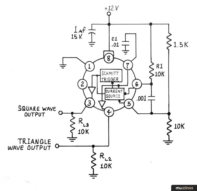
For those of you not familiar with the 566 VCOs, they look like this:

and I have always suspected that they were defective 565 Phase Locked Loops in which only the oscillator portion was operational.
The Vcc pins is the supply (this chip likes to work with from 10-24 volts across it), GND is ground and the pins labeled Square Wave Output and Triangle Wave Output are self-explanatory. It's the Timing Capacitor, Timing Resistor and Modulation Input pins that we are really concerned with.
Whenever you see one of these devices used in a circuit it is invariably hooked up something like this:

Like most VCOs, the 566 is a relaxation oscillator at heart. The timing capacitor charges at a rate set by the timing resistor. As the capacitor charges, the voltage across it increases until an upper threshold set by the internal Schmitt Trigger is reached, at which time the Trigger switches causing the Current Source to provide a discharging current rather than a charging one. The voltage across the capacitor decreases until the lower threshold of the Schmitt is reached, whereupon it switches again and begins once again the charging cycle.
Because the charging and discharging is done with a constant current the voltage across the capacitor is a triangular wave which is buffered by a very simple internal amplifier before appearing at the package's Triangle Wave Output pin. The output of the Schmitt is the Square Wave.
There is some control over the current supplied to the timing capacitor provided by the Modulation Input pin in this configuration, but it's minimal, and it also has some really raunchy problems for our uses.
First, the control voltage input is referenced not to ground, but to supply. To increase the frequency you DECREASE the control voltage.
No sweat, you think, an inverter will do this. Indeed - but - a constant voltage must be summed into the inverter's input to offset its output from ground up to the reference level required by the 566. The implication of this is that the off-setting voltage must be CONSTANT. Very constant because any variation in it will result in the response curve of the VCO not intersecting zero; i. e. you will not reach exactly zero frequency for exactly zero control voltage.
Secondly, the linearity is not good enough for our purposes for a couple of reasons:
a) The current source (when simplified somewhat) is essentially like every other current source in the world and can be thought of as a single transistor. Like this:

The actual current source in the chip, unlike the illustration above is bi-lateral (supplies charging and discharging current) but this representation is useful for our purposes. Most of us already know what's wrong with this; the diode equation that governs the current flow through the transistor is non-linear and extremely temperature dependent.
b) The buffer that is supposed to isolate the triangle wave that appears across the capacitor is not ideal so that some of the current that is supposed to be charging this capacitor is actually being diverted into the buffer - and this represents an error.
Most people get this far and go: YECH this will never work. BUT IT WILL just not like this.
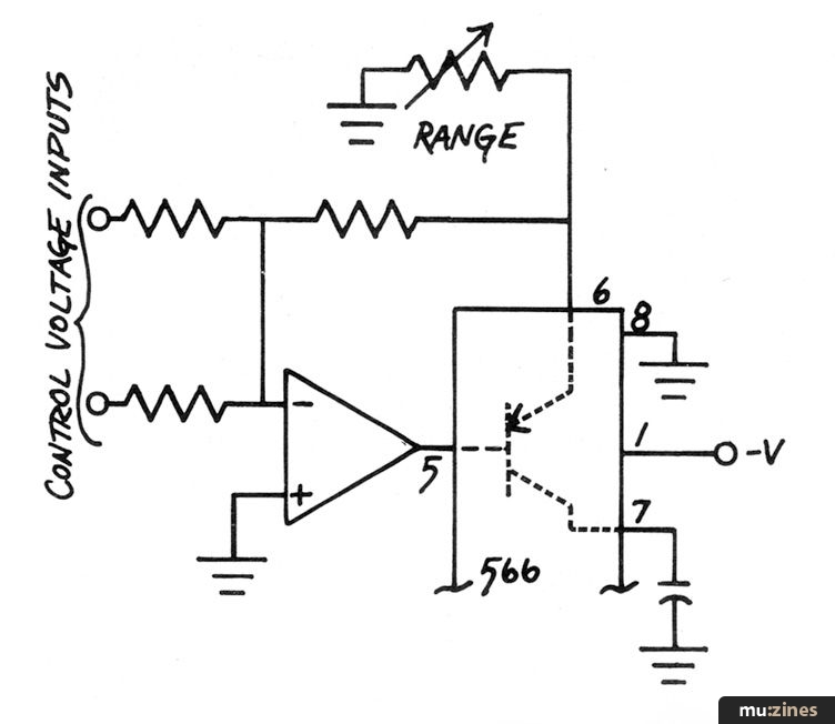
The key to using these devices is turning the "deficiency" in problem (a) above into an advantage. Like this:

Recognize it? It's a lot like the front end of a 4720 oscillator. Here the operation of the current source has been linearized by placing it within the feed-back loop of the summing amplifier. Happily, this change also permanently ground references the input control voltages without having to worry about off-setting problems.
Notice that the 566's supply pins are slightly different here; the chip is now powered from Gnd and the negative supply.
Better, but if you actually hook one of these up and watch it on a 'scope you'll see some strange things. At higher frequencies you will begin to notice that this waveform is not a triangle anymore, it sort of slumps into a ramp - and pretty soon after that it dies completely.
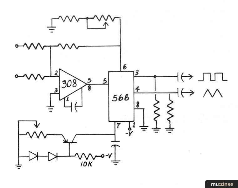
What you're seeing is the error resulting from that imperfect buffer on the triangle output. It's sinking a constant amount of current that really should be going into charging the capacitor. It's not noticeable at high frequencies because at high frequencies the error current is small compared to the charging/discharging current. We can "fix" this by installing an out-board current source to compensate for the lost current, like this:

and this is a complete VCO producing triangles and squares. With the values shown, total usable frequency range is easily 16 Hz. to 16 kHz. and linearity is adequate for our purposes once the current compensator has been properly adjusted. You adjust it in the same manner as you would a "zero" control on one of our other oscillators.
Oh, and before I forget to mention it; these same tricks will work on the 8038 type VCO chips.
THE APPLE CONNECTION
The world is beginning to fill with micro-computers. PETs, TRS-80s, H-8s and H-11s; everybody wants to get into the act. The amazing part of this is:
IT HASN'T REALLY EVEN STARTED YET
The personal computer is as fundamental an addition to mankind's bag of technological tricks as any that has ever happened. As basic as television and radio. A recent issue of Scientific American pointed out that just as the industrial revolution freed men's bodies the personal computer will free their minds. We will keep our fingers crossed that this "freedom" doesn't lead to atrophy. Or worse yet, some sort of intellectual anarchy. The basis for freedom is, after all, discipline.
And, before we get off the subject (what is the subject?) why has no one yet done research on the subjective aspects of computers - their psychological impact. The narcissistic implications of sitting (by choice) at the terminal of a computer hour after hour. Isn't it this "self-love" that is the basis for our fascination with these things? A very sophisticated window into our souls. The ultimate slave. Mental masturbation.
That was somehow supposed to lead us into the Apple II interface card (though I now have forgotten how). Oh well, damn the non-sequitur, full speed ahead.
The Apple II is nice. One of the nicer things about it is that it really exists - and has for at least six months. You can really go into your local computer store and see one. And play with it. Don't buy it there, though, buy it from us.
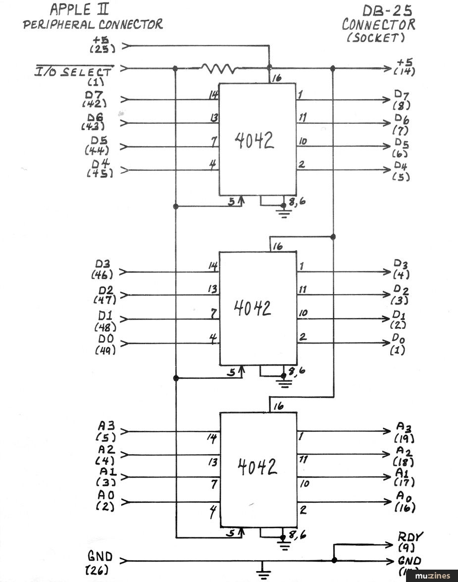
Another nice thing about them is that they are easy to interface to. Inside the case, along the back edge of the circuit board, is a row of eight 50 pin edge connectors. I don't know what all Apple has in mind to go to these connectors (you would probably be safe guessing things like printers and disk drives) but they absolutely could not have made them any easier to use with our synthesizer stuff. Here's ALL the circuitry you need:

The I/O SELECT line on the Apple II peripheral connectors is an active-low signal line that indicates a read or write operation from or to any one of a contiguous block of 256 addresses. Which block is a function of which connector. For example, the I/O SELECT line of peripheral connector #7 (the one we usually use) goes low for the addresses in the range $C700 to $C7FF. When low, this line causes new data to be strobed into the 4042 latches. The outputs of these latches are the inputs to peripheral module you are controlling.
If that module is an 8780 D/A, the connections to the D/A's "D" connector should be as shown in the 8780 manual.
For those times when a QuASH is also part of the system, an additional 4042 is used to simultaneously latch the 4 least significant bits of the address line.
Tieing into an Apple II buys you quite a few things (color graphics to go with your music, etc.) and one of the biggest of these is a relatively nice BASIC.
BASIC, as most everyone knows by now, is an acronym for Beginners All-purpose Symbolic Instruction Code, and it is one of the nicer high level languages for beginners. If you know absolutely nothing about BASIC (or just a little) I highly recommend "BASIC" by Robert Albrecht and LeRoy Finkel and Jerald R. Brown. Published by Wiley and Sons.
BASIC is a very "conversational" language. It uses statements like:
LET A=B+C
(which adds B to C and replaces A's current value with the result)
GO TO 10
(each statement has a number, this means go to statement #10)
FOR N=1 to 10
...
...
NEXT N
(which "loops" through the instructions represented by the first with N=1 then N=2, up to N=10)
Most BASICs have a POKE instruction which allows you to write data directly to a specified memory location (as opposed to simply assigning it a variable name to be put who-knows-where by the interpreter). Since I/O operations on the Apple II are memory mapped (it uses a 6502 MPU), the POKE statement is tremendously useful for output operations also.
Most POKE instructions take the form POKE (A, D) where the two arguments are A - address and D - data to be written to that address. About the only tricky part of using them is that the two numbers are invariably specified in programming as decimal numbers. And, the Apple II can be particularly confusing because numbers greater than 32676 must be expressed as negative numbers. The addresses that we're using as output ports are greater than 32676, but I can save you a little time on the calculations and just list them:
| (1) | (2) | (3) | (4) | (5) | (6) | (7) |
| -12311 | -12567 | -12823 | -13079 | -14335 | -14591 | -14847 |
| . | . | . | . | . | . | . |
| . | . | . | . | . | . | . |
| . | . | . | . | . | . | . |
| -12056 | -12312 | -12568 | -12824 | -13080 | -14336 | -14592 |
I didn't list the address range of slot #0 because it's reserved for something that the Apple folks have in mind.
If I have some note N that I want to play, I can do it with the statement: POKE (-14592, N) which assumes that I'm outputting the data to the first output location slot #7.
Simple.
But there are also some tricks involved in determining what N is going to be, and to discuss these I must remind you that of the 8 bits of data that the 8780 accepts, six (the low-order 6) are converted to a control voltage while the high order 2 are used as control flags. Since 6 binary digits can express a decimal number between 0 and 63 (64 numbers), this is the range of the D/A in semi-tones. 64 is the magic number, remember it.
In binary, the decimal numbers 0-63 will "count" like this:
| decimal | binary |
| 0 | 00000000 |
| 1 | 00000001 |
| 2 | 00000010 |
| 3 | 00000011 |
| . | ... |
| . | ... |
| 63 | 00111111 |
Notice that in this sequence the two most significant bits of the binary number remain both zeros. Since these are the "trigger" bits, the trigger flags never get set.
I'd really like to impress you with a lot of snappy digital magic, but don't feel that I could get away with it. It's pretty obvious that setting the flags is a simple addition process. If we want to play note #3 with the low order trigger bit set we simply add:
| decimal | binary |
| 3 | 00000011 |
| +64 | +01000000 |
| 67 | 01000011 |
and do a POKE (-14592,67). To set the most significant trigger bit we can add 128 (2 x 64) to whatever note is to be played. To set both flags add 192 (128 + 64).
Clearing flags is the reverse procedure. If we're playing a note with a specific flag set and want to clear it we can subtract:
64 for low order flag
128 for high order flag
192 for both flags.
We need to keep track of what's going on, of course, particularly when clearing flags with a subtraction - otherwise we might actually wind up with a negative number as our output. That won't work.
Usually, it is easiest when programming to use the flag-setting addition as an expression directly in the POKE statement's data argument.
This:
100 POKE (-14592, N+128)
110 FOR R=1 to 20 : NEXT R
120 POKE (-14592, N)
...
...
for instance, is a short program that will cause some note N (determined in previous programming steps) to be played first with the high order trigger flag set and then - after a delay determined by how long the FOR-NEXT loop at statement 110 takes to execute - again with the flag lowered. This would be like playing a note from the keyboard and holding the key down for the duration of the FOR-NEXT before releasing it.
Transposing things into a new key signature is no big problem. To transpose a note up an octave simply add 12 (the number of semi-tones in the equally tempered scale) and to transpose down an octave subtract 12. To transpose up by an interval of a third add --. Down by a third subtract --.
You get the idea.
Suppose that we wanted to write a short program that would play only the whole tones in an octave - how can we do it? One thing that we can't do is simply count because that would play all the notes and playing just whole notes there will be some we want to skip: specifically, the 2nd, 4th, 7th, 9th and 11th.
Here's a way to do it (an OK way, there are probably better) that will also be useful for converting letter-name entries from an ASCII keyboard into the decimal number required to produce the desired note.
First, we define a literal (text-string) variable as follows:
20 LET N$="C-D-EF-G-A-B"
The spacing of the note names within this variable, you will note, is the same as the distribution of the whole notes on an AGO keyboard with the hyphens replacing the accidentals. Now the Program:
100 FOR N=1 TO 12
120 IF N$(N, N)="-" THEN 150
130 POKE (-14592, N+D+128)
140 FOR R=1 TO 200: NEXT R
150 NEXT N
160 END
And since the Apple BASIC is slightly different from most I should point out that the "IF N$ (N, N) ..." business is this language's way of dissecting a string.
It says, "if the constituent characters of the string N$ between the Nth character and the Nth character (in other words, the Nth character) ... etc. ". Various BASICs will have various ways of accomplishing this same thing, most of them. Some have no provisions for "string manipulations" at all - avoid them.
When the little block of code above [runs] it sets N first equal to 1 (statement 100), checks to see if the first character in the string is a hyphen (120), finds that it is not so does not take the branch to statement 150 and instead POKEs the first note (plus some transposing displacement D-plus the flag-setting 128) to the D/A (130), decays (140) and then goes to get the next value for N (150- 100). With N now equal to 2, the second character N$ is found to be a hyphen so the branch at statement 120 is taken to statement 150 (NEXT N) without playing the corresponding note. The variable N increments again (it is now 3) and on going through the program finds that this represents a valid note and plays it.
With a couple of minor changes to this program, it can also be used to convert ASCII keyboard entry of note names into the required decimal numbers. The stages consist of adding a new instruction:
90 INPUT "ENTER A NOTE", A$
changing statement number 120 so that it is now:
120 IF N$(N, N)#A$ THEN 150
and here I need to explain that in Apple BASIC "#" is a symbol for "different from" (most other BASICs use back-to back "greater than" and "less than" signs - <>).
There isn't an appropriate symbol on an ASCII keyboard for flats, so you may want to play every flat at the corresponding sharp and use the "#" symbol. From a programming standpoint, you may want to calculate the decimal equivalent of the sharp by noting if the sharp symbol is part of the note that was input and adding 1 to N if needed. A single statement will do it:
IF A$(2, 2) = "#" THEN N=N+1
The Apple II interface card is available from PAIA for $14.95 postpaid.
More from these topics
Voltage-Controlled Clock for Analogue Sequencers |
The Ins and Outs of Digital Design |
Workbench |
Software Support - Hints, Tips & News From The World Of Music Software |
Mac Notes |
Apple Notes |
Augmenting the 3750's Memory |
Electro-Music Engineer - Tuning Up — A Review of VCO Calibration Methods (Part 1) |
PET/Muse - Interfacing Paia Synthesizers to PET Computers |
Atari Notes |
Atari Notes |
 ST Notes |
Browse by Topic:
Computing
Electronics / Build
Publisher: Polyphony - Polyphony Publishing Company
The current copyright owner/s of this content may differ from the originally published copyright notice.
More details on copyright ownership...
Feature by John Simonton
Previous article in this issue:
> Patches
Help Support The Things You Love
mu:zines is the result of thousands of hours of effort, and will require many thousands more going forward to reach our goals of getting all this content online.
If you value this resource, you can support this project - it really helps!
Donations for January 2026
Issues donated this month: 0
New issues that have been donated or scanned for us this month.
Funds donated this month: £0.00
All donations and support are gratefully appreciated - thank you.
Magazines Needed - Can You Help?
Do you have any of these magazine issues?
If so, and you can donate, lend or scan them to help complete our archive, please get in touch via the Contribute page - thanks!


