


Magazine Archive
Home -> Magazines -> Issues -> Articles in this issue -> View
Sine VCO | |
Article from Electronic Soundmaker & Computer Music, June 1984 | |
A high-purity 5½ octave voltage controlled sine wave oscillator. Design by David Strange.
Voltage controlled oscillators are used extensively in musical synthesizers and, as the name suggests, a DC voltage input is made to set their operational frequency. This provides a very versatile element which can be used either directly controlled from the keyboard or via other synthesizer elements, such as ADSR generators, low frequency oscillators, etc.
The VCO described here is capable of generating a sine wave frequency over a 5½ octave range from a control voltage of 0 to 1 volt. This range, however, may be adjusted down to cover less octaves if necessary. Setting up and tuning is very simple, and the provision of square and triangle waves is just as easy.

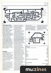
Fig. 1
(Click image for higher resolution version)
The Circuit
The circuit consists of a non-inverting input amplifier (IC1) with a variable gain of x2 to x12 adjusted by means of VR2. VR2 sets the ultimate frequency obtained from a 1V input and therefore the range of frequencies overall (VR1 is used to remove any offset voltage from IC1 at the higher gains).
IC2 is a mixing amplifier and the voltage derived from IC1's output is summed with a variable negative voltage derived from VR3. VR3 is used to adjust the lower frequency limit of the VCO and since this is normally done when the input from IC1 is at 0V, the adjustment is not inter-reactive with VR2.
The output of IC2 is connected directly to the frequency modulation sweep input of IC3 which is a voltage controlled waveform generator. The frequency output from IC3 is dependent upon capacitor C1 and the control voltage on its pin 8. VR4 is used to set the time symmetry of the output and VR5 and VR6 adjust its purity in the positive and negative voltage domains.
The output of IC3 needs to see a relatively high resistance (100k is recommended), and so IC4 is used simply as a voltage follower to obtain a low resistance output.
Construction
Using the printed circuit board which is available for this project, construction is a very straightforward process with few pitfalls.
Firstly, a decision should be made as to whether VR2 and VR3 are to be preset on the PCB or brought out as front panel adjustments on the box chosen for the project. The latter probably provides for the most versatile arrangement, and for ease of tuning perhaps screwdriver adjusted multiturns could be used. If the choice is made to use external adjustments, PC pins should be inserted into the board to pick up the connections. Such pins are the first components that require loading into the board because these need a fair amount of pressure to be exerted which might otherwise damage any previously loaded components. Pins provides a good anchor point for all external connections to the PCB and are much more reliable than directly soldering in a wire where the danger is that the copper track will lift off with only a small force. Do not forget to solder the pins after they are pushed in.
IC sockets should be used for all the IC's and after these are soldered in, a frame of reference is provided for the locations of all the other components which can now follow. C1 used in the prototype was 100n, but this may require some modification as described in the line up instructions.
Power Requirements
The VCO relies on a regulated power supply for its frequency stability. Since the current drawn is consistent (approximately 25mA per rail), very little change in voltage will occur due to current demand. There will be changes in mains voltages to the power supply though, and will be reflected through to the power rails if some form of stabiliser is not used.
If a stabilised dual rail supply is not available a suitable voltage regulator is shown in Fig 2. It uses two 15V fixed regulator chips to give a constant output supply voltage and can be built on a separate PCB. The input to the regulator board can be from a mains transformer having a split secondary of 20V each side and capable of supplying 50mA per section.

Fig. 2
(Click image for higher resolution version)
Setting Up
The voltage supply to the VCO should not exceed ±18V otherwise damage will occur to the IC's. Note also, that IC3 dissipates quite a lot of power (750mW) and will appear to run hot — this is quite normal and not necessarily caused by a fault so do not be too alarmed if it burns your fingers.
VR1 needs adjusting first to remove any offset from the output of IC1 and so with the board powered up connect a voltmeter between pin 6 of IC1 and 0V. The input end of R1 should be grounded to 0V and VR2 adjusted to maximum resistance for the measurement. VR1 is adjusted until any voltage appearing on the output of IC1 is removed or at least minimised as much as possible. VR1 needs no further adjustment.
Next, connect the source of control voltage you intend to use with the VCO. Also connect a suitable amplifier and speaker to the output of the VCO so that you can hear the output. Set the input control voltage to about half of its range (say 0.5V) and with the aid of an oscilloscope (or by ear) adjust the symmetry of the output with VR4 and the purity with VR5 and VR6. It may be necessary to slightly scale the control voltage range with VR2 to make this procedure possible. The sound should be a smooth sine with no distortion or harshness (though adding these later may be desirable).
With the purity and symmetry adjusted, tuning is the next step. Your control voltage should be minimised and VR3 adjusted to set the lowest frequency you require. When this is done your control voltage should be set to its maximum (1V) and VR2 adjusted to the maximum frequency you require. VR2 settings will have no effect on the lower frequency when the input to the VCO is zero.
It may be found that the ranges of VR3 and VR2 do not quite cover the frequency range you require and therefore some adjustment of C1 becomes necessary. The capacitance of the miniature layer type capacitors recommended can be changed quite easily and no difficulty was found in tuning, at the lower end of frequencies: to the first piano note (275Hz) for instance. The procedure adopted was to gently split off, layer by layer, sections from the side of the capacitor with a sharp scalpel. Fewer layers are removed as the frequency required is approached. A perfect tune can finally be achieved with the help of VR3.

Fig. 3
(Click image for higher resolution version)

Fig. 4
(Click image for higher resolution version)

The PCB foil pattern for the Sine VCO.
(Click image for higher resolution version)
Parts List
| R1,R2,R3,R4,R5,R8,R13,R14 | 10k |
| R6 | 56k |
| R7 | 5k6 |
| R9 | 10m |
| R10, R11 | 4k7 |
| R12 | 15k |
| R15 | 100k |
| R16 | 560R |
Presets | |
| VR1,3 | 10k |
| VR2,5,6 | 100k |
| VR4 | 1k |
Capacitors (min metalised layer) | |
| C1 | (see text) |
| C2 | 1u 100V |
Semiconductors | |
| D1 | IN914 or 1N4148 |
| IC1, IC2 | uA741 |
| IC3 | ICL8038 |
| IC4 | LF351 |
Miscellaneous | |
| Connecting wire, PC pins, Box, PC Board, Fixing Screws and Spacers, Audio Sockets, Power Socket (if used). | |
More with this topic
 Electro-Music Engineer - Tuning Up — A Review of VCO Calibration Methods (Part 1) |
 Electro-Music Engineer - Transistor Power Amplifier Surgery |
 Soldering On (Part 1) |
 Short Circuit |
 Workbench - Impedance. What is it?! |
 Sample & Hold Modification - Provides Note Bender |
 Adding Fine Tuning To Standard Controls |
 |
 Workbench - CHECKA |
 Amdek DMK-200 Delay Machine Kit |
 Gnome Instrument Interface - Using the 2720-11 Envelope Follower |
 Lab Notes: Potpourri & The Apple Connection |
Browse by Topic:
Electronics / Build
Publisher: Electronic Soundmaker & Computer Music - Cover Publications Ltd, Northern & Shell Ltd.
The current copyright owner/s of this content may differ from the originally published copyright notice.
More details on copyright ownership...

Electronic Soundmaker - Jun 1984
Donated & scanned by: Mike Gorman
Feature by David Strange
Help Support The Things You Love
mu:zines is the result of thousands of hours of effort, and will require many thousands more going forward to reach our goals of getting all this content online.
If you value this resource, you can support this project - it really helps!
Donations for June 2026
Issues donated this month: 0
New issues that have been donated or scanned for us this month.
Funds donated this month: £0.00
All donations and support are gratefully appreciated - thank you.
Magazines Needed - Can You Help?
Do you have any of these magazine issues?
If so, and you can donate, lend or scan them to help complete our archive, please get in touch via the Contribute page - thanks!