


Magazine Archive
Home -> Magazines -> Issues -> Articles in this issue -> View
Workbench | |
The Easy LifeArticle from International Musician & Recording World, June 1986 | |
Phil 'DO or DIY' Walsh with a neat and tidy solution to footswitch overkill
Playing on stage is often a confusing tangle of leads, footpedals, switches, dead bass guitarists etc. Anything that makes life a little less of a hassle has to be worth a good long look. If it turns out to be easy enough (and cheap enough) then what the hell? — go for it! Regular sufferers of my column will have sussed by now that I am harping back to an old, familiar theme. Yes folks, my Campaign for Really Ameliorated Playing (CRAP) rears its ugly little head again. (Ameliorated? What? Oh, look it up in the dictionary — I had to!)
This present little skirmish in the campaign started when I was watching a band in a small club in Watford. They were a semi-pro three piece with bass, drums and guitar/keyboards. A particular strength of the band were the harmony vocals but watching the antics of the guitarist between the end of a number and the beginning of announcements/chat was by far the most entertaining part of the set. With all the grace of a Yorkshire clog dancer he was leaping around pushing a variety of foot pedals. In the interests of my ever curious reader I donned a cunning disguise (borrowed from Billy Punter), and with thoughts of upstaging Beatroute and the PA column, I sidled up to the band during the break.
It turned out that their vocals were fed through a fairly standard PA mixer amp but they processed them via the echo send/return sockets by feeding the echo send to a digital echo unit, set as an ADT which then slaved into a second digital echo set for slap back echo and thence back into the echo return socket. In addition small amounts of the amplifier's built in reverb were added to the returned signal. This gave rise to three footswitches all of which had to be switched off prior to any announcement ("There's a taxi for Bloggins waiting", "Let's all sing happy birthday to Amanda", "What about a drink for the band?" etc) and then switched on again for the next number. Now for semi-pro and amateur bands who don't have the benefit of a sound engineer this is a bit of a hassle, not to mention the tangle of leads that the footswitches need to operate them. One solution, of course, is to build all the footswitches into one case, with the operating buttons close enough together to be operated all together with one push of your foot. In practice this is pretty unsatisfactory for two reasons:
1. If you don't push the buttons with your foot at just the right angle it is possible to miss one.
2. It still doesn't solve the problem of all those leads trailing around your feet.
A much more elegant and tidy answer is to let a little electronics do the work for you.
The circuit I am about to suggest will fit into a box about the size of a cigarette packet and will switch up to four echo/reverb/outboard effects units simultaneously using a standard effects footswitch. The heart of the unit is an integrated circuit chip containing four infra-red operated transistor switches. This is, in fact, virtually all you need, the only additional components being five jack sockets and a battery. To increase the unit's versatility I've also added a low voltage power socket but this is strictly optional. The heart of the unit is the ISQ74 or ILQ74 opto isolator chip. This should be available from any decent electronics component shop but in case of difficulty it is obtainable from TK Electronics, (Contact Details). To save hassle you can phone them 24 hours a day and quote your Access or Barclaycard number. I have given the relevant stock numbers against the parts list.
The prices I've quoted may be a little out of date but serve to give a rough idea of the costings.

FIG 1. VEROBOARD TRACK SIDE VIEW
The piece of Veroboard I've listed is much larger than you actually need, but is the smallest size available. Cut it down to 13 rows (copper strip) of 18 holes and store away the rest for another day. Figure one shows the eight cuts that must be made in the tracks – this can be done by twisting a ¼" drill bit against the copper. Referring to the component side view of the board (figure two) fit the IC socket with its notch towards the top of the board, turn the board over and solder itin place. Fit the three wire links and the four resistors into the board and solderthem.

FIG 2. COMPONENT SIDE VIEW
Solder 3" lengths of insulated wire to circuit board points E17 to LI7 (eight wires) and also one piece to B2. If a low voltage power socket is to be used solder another piece of wire to K7. Solder the black battery connector lead to K9.

FIG 3. BOX DRILLING DETAILS
Put the circuit board to one side and get out your drill. With the lid uppermost drill five holes for the ¼" jack sockets and a smaller hole for the 3.5mm low voltage socket (if fitted). Figure three shows the idea. Push the chip into the socket with the notch orientated as shown in Figure two. Using double sided sticky pads, stick the circuit board to the bottom of the box and then fit the jack sockets into the holes. Connect up the wiring as shown in figure four. If the low voltage power socket is not used then the red battery lead connects directly to the footswitch jack socket 'tip' tag. Wrap the battery in a little foam and screw on the box lid.
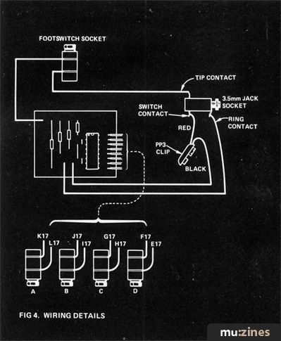
FIG 4. WIRING DETAILS
The unit is switched on by plugging in a standard footswitch into the footswitch socket. A jack to jack lead then connects between the effect unit's footswitch socket and one of the four jack sockets – up to four different effects can be switched simultaneously. The unit only draws current from the battery when the effects are switched off. Should you only require two effects to be switched then removing the wire link G10-J10 from the circuit board will disable switches C & D giving approximately twice the life from the battery. Obviously if you've opted for the low voltage supply this is irrelevant. The low voltage supply should be brought in via a 3.5mm jack plug with the positive connection to the jack plug tip. If the unit works with the battery but not with the power supply then you have either got the wiring of the 3.5mm jack plug reversed or you need to switch around the red battery lead and wire from the footswitch socket where they are soldered to the 3.5mm jack socket. (If it's been a really bad day you could have both things wrong!)
With the one unit you'll be saving time between numbers, and money on tap dancing lessons!
Parts List
| £ | ||
| 7 off 16-pin dil socket | 450102 | 0.15 |
| 1 off Quad opto isolator | ILQ74 | 1.80 |
| 5 off ¼" mono jack socket | 450120 | 1.10 |
| 1 off pack of 470 ohm resistors (10) | 0.10 | |
| 1 off 3.5mm switched jack socket | 450117 | 0.15 |
| 1 off Veroboard | 80121070 | 0.95 |
| 1 off plastic case | 601002 | 0.90 |
| 1 off PP3 battery clip | 303210 | 0.08 |
| p&p | 0.75 | |
| Total | £5.98 |
More with this topic
 Projected Developments |
 Technically Speaking |
 Dual Voltage-Controlled LFO |
 Workbench - Go Active! |
 The Matinee Organ (Part 1) |
 Modify Your "Phlanger" - for Lower Noise |
 PA Signal Processor (Part 1) |
 Building A Bionic Sax |
 BeeBMIDI (Part 1) |
 Studio Earthing Techniques - Interconnect (Part 1) |
 Digital Signal Processing (Part 1) |
 Workbench - Signal Processors - Frequency Response Modification |
Browse by Topic:
Electronics / Build
Publisher: International Musician & Recording World - Cover Publications Ltd, Northern & Shell Ltd.
The current copyright owner/s of this content may differ from the originally published copyright notice.
More details on copyright ownership...

International Musician - Jun 1986
Feature by Phil Walsh
Help Support The Things You Love
mu:zines is the result of thousands of hours of effort, and will require many thousands more going forward to reach our goals of getting all this content online.
If you value this resource, you can support this project - it really helps!
Donations for May 2026
Issues donated this month: 0
New issues that have been donated or scanned for us this month.
Funds donated this month: £0.00
All donations and support are gratefully appreciated - thank you.
Magazines Needed - Can You Help?
Do you have any of these magazine issues?
If so, and you can donate, lend or scan them to help complete our archive, please get in touch via the Contribute page - thanks!