


Magazine Archive
Home -> Magazines -> Issues -> Articles in this issue -> View
Build It Yourself | |
Article from Electronic Soundmaker & Computer Music, June 1984 | |
At last the instructions
A step-by-step guide to the construction of electronic projects, presented in ebullient style by Peter Luke.

A glance through any issue of ES&CM will reveal a number of constructional projects. These designs often match the performance of commercial equipment, yet can be built for a fraction of the cost of an off-the-shelf, ready built unit. In some cases magazine designs will offer facilities that would be difficult to find in a commercial product. Obviously then by mastering the skills necessary to put together the projects appearing within these pages you will be able to not only save money, but also to tailor the electronic equipment you use to your exact requirements.
This article sets out to show that, although at first sight a circuit diagram together with associated overlays and PCB patterns can seem rather more than confusing, with a few basic bits of information at your finger tips, it all becomes clear. We'll also try to keep it 'jargon free' but as the occasional bit of technospeak crops up, the term will be fully explained.

Buyer's guide
It's difficult to know where to start an article of this nature but, as the first thing you will need to do once you have decided to go ahead and build a project is to get hold of the components, a few hints and tips in this direction would seem to be a sensible starting point. In the case of some projects a complete kit, from PCB — that's shorthand for Printed Circuit Board, an item that we'll describe further in a little while — to the last nut and bolt, is available. In this case it is only necessary to get your hands on the necessary 'readies' and in a couple of days you'll be ready to start construction.

If a full kit of parts is not supplied by anyone it will be necessary to do a bit of shopping around. ES&CM has it's own PCB service so there should be no problem getting hold of this item. As to the rest of the components, the only sensible way to go about getting hold of these is to obtain a catalogue from one of the larger component suppliers. Look through the adverts and send off for any catalogue that you can find. They usually cost between 60p and £1.50, but the money you spend on them will be well worth it. You could also try your local branch of W H Smith as the excellent Maplin catalogue is available from many of their stores. You may also find the recently published Ambit tome at the same store. Go ahead and buy both, they're worth it.
When you get your catalogue, turn to the index page and then study the parts list of the project you have selected as your first venture. You'll see that the components in the parts list are divided into various sections, usually resistors, capacitors, semiconductors and the dreaded miscellaneous section. As to the first three categories, the index will have corresponding entries. Flip to the appropriate page and with a bit of patience you should be able to find an entry in the catalogue that exactly matches the items in the parts list. Most mail order companies produce an order form which makes it easier both for you to list the components and for the company to make sure they send you exactly the right parts. Use the form, it really will make life easier.
With your collection of catalogues any item that is not in one may well be offered by another outfit but beware of skipping between a number of catalogues and choosing the supplier who offers the cheapest price. You have to bear in mind that most companies make a charge for postage and packing and that if you end up ordering from many different sources, you may well find that any savings made on the cost of individual items have been swamped by the postage costs.

Before moving on, we must mention another source of components, namely your local store. Those of you living in the London area will find a collection of shops in the Edgware road that between them are likely to offer all the bits and pieces you are likely to need. Look for companies in your area and pay them a call — make sure they are prepared to deal with callers however, as some suppliers are strictly mail order only. The Tandy chain of shops also offers a limited range of components and the shops are to be found all over the country. The prices at Tandy tend to be somewhat higher than say Maplin, but you may well find that the convenience of shopping locally outweighs this.
The major advantage of shopping in person, is that most shops will be willing to put together all the components for a project from the parts list. They will also be able to advise on any substitute components if one of the items is not in stock. It is often the case that there are many different types of component that can be used as an alternative to the one supplied. Making a decision on the substitute component however is not for the beginner. As we've said, component shops are often willing to put together a kit for a caller but, if you are to ask them to do this, please do not call in on a Saturday afternoon when there will be long queues of people waiting to be served.
Identity Parade
Whether you have ordered a complete kit of parts or have shopped around for yourself, when you come to start construction you will be faced with a small pile of components that will have to be matched up to the parts list. At this point it is worth stressing that before you even contemplate soldering the components to the PCB, you should make sure that you have identified each item in the parts list and that you have all that it necessary to complete the design.
The best way of sorting out the components is to get a square of polystyrene foam, a ceiling tile is ideal. Cover this with a thin sheet of paper on which you have written down all the items in the parts list. As you select each component push its leads down into the foam. Adopting this approach makes it both easy to lay your hands on any component at the construction stage, but also highlights any missing items.
As a check on the accuracy of the parts list, yes even magazines like ES&CM have been known to make the odd mistake, it is a good idea to match the components to, not the parts list but the circuit diagram — in theory they should be the same. The best place to start is with the semiconductors, simply because there are likely to be fewer of these than any other group of components. Semiconductors can be either single transistors or DIL— that's Dual In Line, a description of the way in which the IC's pins are arranged — Integrated Circuits (ICs), which are in effect a collection of tens, sometimes hundreds of transistors on a single silicon chip. The section of circuit diagram shown in Fig 1 is typical of the kind of circuit found in ES&CM and will serve to introduce the circuit symbols of the various components.

Fig. 1
The semiconductors in this circuit are Q1 and IC3a and IC3b. Q1 is a transistor, and transistors are always shown drawn as in our example circuit diagram, the only minor point being that in some cases the tiny arrow pointing away from the centre of the transistor's symbol may in some cases point toward the centre. This minor point differentiates between the two mayor types of devices NPN and PNP. Nowadays most transistors are NPN like the one in the circuit and in any case whether a transistor is PNP or NPN will not concern you when you are building up a circuit.

Fig. 2
The physical appearance of a transistor is shown in Fig 2. This shows a small body of either plastic or metal together with three leads. The three leads correspond to the emitter, base and collector terminals, denoted by e, b, and c on the diagram. The transistor will have some kind of orientation mark on its body, this is often a small metal tag in the case of a device with a metal case or a flat (but no tenants — Ed) on one side in the case of a plastic encapsulation. In either case the component catalogue should give a drawing to show which lead is which for the particular device you have — we said the catalogues were handy to have around.

Fig. 3
The other semiconductor in the diagram is an IC and as we've said these are usually in a DIL package such as the one shown in Fig 3. The device type will be printed on the top of the IC making identification easy. The only point to note is that sometimes manufacturers add 'in-house' codes of their own so that a 741 IC may be shown as NE741C — the point to note is that somewhere amongst the collection of numbers or letters the device number appears as a consecutive string.
You'll see from the circuit diagram that all the pins of an IC are numbered, starting at 1 and going up to 8, 14 or even higher. The only thing needed to orientate an IC correctly is a knowledge of which pin is pin 1. To accomplish this the IC body will have either a notch on one of the narrow sides, as shown in the diagram or will have a tiny dot printed on the device. In both cases with the notch (dot) pointing away from you, pin 1 is the leftmost pin.


Couldn't Resist It
Having placed all the semiconductors alongside their place in the sheet of foam, the next group of components to identify are the resistors. On our circuit diagram these range from R9 to R13, although on a complete diagram the numbering would start from R1. Each resistor will have alongside it an indication as to its value. This is not an article on theory so we will not bog you down with such things as Ohm's law and power dissipation factors, but will restrict ourselves to the information necessary to identify a particular resistor.
Taking R9 as the starting point, this is shown as 15k. The k stands for kilo and is the metric multiplier of 1,000. Thus 15k means 15,000 Ohms. In the case of both transistors and ICs the identity of the component was clearly marked on the body. With resistors however the devices are too small to have the value stamped on them, the size of the type 15000 is probably larger than the majority of resistors. The marking adopted in fact takes the form of a series of coloured bands each determining one of the digits of a resistor's value. Fig 4 shows the outline of a typical resistor together with the series of coloured bands.
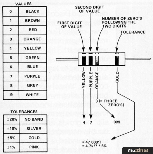
Fig. 4
The table shows which of the colours represent the numbers in the range 0 to 9 and the diagram of the resistor shows the order in which the bands appear. In the case of R9 a 15k resistor, you can see that the first band will be brown, the second green (representing the 5) and the third, or multipler band will be orange (representing the three zeros of 1,000). Resistor R11 is shown as 4k7 and this simply translates as 4.7x1,000 or 4,700 Ohms. The marking on this resistor would be Yellow, Purple, Red.
Other multipliers that you will come across are M standing for 1,000,000 and just plain R which means there is no multiplier, thus R12, 100R, is just 100 Ohms. Work out for yourself the marking on R13 and R12.


Before leaving all this talk about coloured bands it is probably worth pointing out that some men are colour blind to a certain extent — this is nothing to worry about and comes as a natural result of maturity. However, if you find that you can't tell a green from a brown or a red from an orange get someone else, preferably young, shapely and female to do the sorting for you.
If you're anything like most people, when you reach the last stages of marrying up your resistors to the parts list you'll probably find that you're left with a 15k resistor in your hand when the only blank space is for a 1k5 resistor. It's probably your mistake on a multiplier, at this stage it's easy to check, but it does highlight the need to sort out all the devices before starting construction as once something is soldered in it is considerably more difficult to remove.
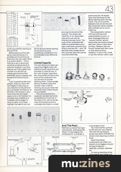
Limited Capacity
The next devices to select are capacitors. Fig 5 shows the outline of some capacitors you are likely to come across. In the case of larger capacitors the value will be printed on the body of the component and you will have no trouble selecting them. Some smaller devices however adopt the resistor colour code for marking, but as you have now mastered that(!) there should be no problem.

Fig. 5

The circuit symbol for a capacitor can take two forms as typified by C5 and C8. In the case of C5, one of the two lines forming the symbol is unshaded and there is a small plus sign at one end of the symbol. This means the capacitor is an electrolytic type and it can only be inserted one way round. The body of the component will either be marked with a plus sign or will have a groove on its body to indicate the + end. C8 has both lines shaded and in this case the capacitor can be mounted either way.
And The Rest...
Well that's covered the major components, what about the others? In the diagram the component D1 is a diode, a semiconductor. All diodes have only two leads but the device will only work one way round. The circuit symbol features a bar at one end and the component will be marked with a similar bar for you to match up.
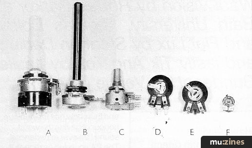
The components marked VR2 and VR3 are both potentiometers or pots. In plain language these are 'volume controls' and as before they are mostly marked with their value in clear black printing. However, if a pot is very small in size the resistor colour code is once again used.
You'll see that the symbols for the two pots vary slightly. VR2 with the bar being a preset type while VR3 with the arrow is one requiring a control knob.

Apart from these components the others in a typical circuit diagram should be easy to identify — switches, sockets, batteries etc.
So having identified all the components and made sure you have everything necessary to build the project it's time to get the soldering iron out and start construction — but that's another story...
More with this topic
 Digital Sampler/Delay (Part 1) |
 DIY Direct Inject Box - A high quality DI box circuit |
 Technically Speaking (Part 1) |
 Digisound Voice Card (Part 1) |
 Powertran MCS1 - Playing with Time (Part 1) |
 The Miniblo |
 Modify Your "Phlanger" - for Lower Noise |
 Studio Earthing Techniques - Interconnect (Part 1) |
 Sample & Hold Modification - Provides Note Bender |
 ElectroMix 842 (Part 1) |
 Destiny Modular Mixer - Input Module (Part 1) |
 The Spectrum Synthesiser (Part 1) |
Browse by Topic:
Electronics / Build
Publisher: Electronic Soundmaker & Computer Music - Cover Publications Ltd, Northern & Shell Ltd.
The current copyright owner/s of this content may differ from the originally published copyright notice.
More details on copyright ownership...

Electronic Soundmaker - Jun 1984
Donated & scanned by: Mike Gorman
Feature by Peter Luke
Help Support The Things You Love
mu:zines is the result of thousands of hours of effort, and will require many thousands more going forward to reach our goals of getting all this content online.
If you value this resource, you can support this project - it really helps!
Donations for April 2024
Issues donated this month: 0
New issues that have been donated or scanned for us this month.
Funds donated this month: £7.00
All donations and support are gratefully appreciated - thank you.
Magazines Needed - Can You Help?
Do you have any of these magazine issues?
If so, and you can donate, lend or scan them to help complete our archive, please get in touch via the Contribute page - thanks!