


Magazine Archive
Home -> Magazines -> Issues -> Articles in this issue -> View
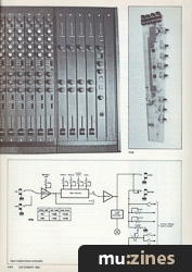
Destiny Modular Mixer (Part 1) | |
Input ModuleArticle from Home & Studio Recording, December 1983 | |
A constructional review of this useful mixer kit.

The Destiny modular mixer, designed by Tim Orr was first described in the magazine Practical Electronics. The truly excellent specifications and facilities, not to mention the flexibility of the modular system however makes it an ideal foundation for any home studio and thus very worthy of further description in these pages.
A complete mixing desk is built up by selecting from a range of 3 modules: Input, Output and Auxiliary. One input module is required for each input to be mixed, but one output module will provide two outputs. The modules can be combined to provide facilities up to an 18 into 4 mixer, although 24 inputs could be handled. The input and output modules, together with an optional auxiliary module and banking plates fit into the module chassis, which comes in bolt-together sections. The modules all plug into a common bus system which not only interconnects them, but also distributes DC power to them. The power supply itself is contained in a separate box to prevent any possibility of hum problems.
Throughout the design, care has been taken to keep the frequency response wide and flat, and the noise and distortion very low. There is no lack of facilities either: PFL, headphone output, talkback microphone, Peak Programme Metering and 3 band equalisation are all provided.
Input Module
Separate switchable mic and line inputs are provided, which are amplified to line level by a variable gain stage. The EQ stage consists of bass, middle and treble controls, where the middle control has an associated frequency control, making it effectively a parametric sweep EQ stage. The EQ section can be switched out completely by means of the Flat/EQ switch. To save on level meters, a +4dBm peak LED keeps a check on signal levels, although the output and auxiliary modules have LED PPMs. Each of the input modules also has its own in-line send/return loop for individual treatments such as flangers and phasers, although the 2 auxiliary buses allow for overall treatments such as reverb and echo. The output from the main fader is split by the pan pot and routed via switches to the output buses. Pre-fade listen (PFL) is also switchable on each input channel. Figure 1 clarifies the input channel functions.

Input module block schematic.
(Click image for higher resolution version)

Input module circuit diagram.
(Click image for higher resolution version)
The circuit diagram shown in figure 2 reveals that RC4558 low noise operational amplifiers are used throughout the input module to achieve the very impressive noise figures; -114dBm for the mic input. S1 a selects either the mic or line input, while S1b simultaneously sets the appropriate gain. VR1 sets the overall gain of the op-amp pair IC1a & b, the output of which can be routed via the EQ section by operating S2. Apart from the quite conventional active bass & treble circuit formed around IC2a, the EQ section also boasts a variable frequency state-variable bandpass filter, IC3a &b and IC4a for the middle control, providing 14dB of boost and cut over the frequency range 440Hz to 4.8kHz. IC4b presents a buffered post-EQ signal to the send socket, JK3. This can be used independently of the return socket for foldback monitoring, although once a plug is inserted into the return socket, the internal loop is broken so that the signal must pass through the external effect loop.
After being attenuated by the main fader VR9, the signal continues on to the output buses via the output selector switches, S4-7 and the pan pot, VR6. The amount of signal put onto the Aux 1 and Aux 2 buses is controlled by VR 7 and VR8. S3 allows the signal to be put on the PFL bus.
The +4dBm peak LED, D2 is driven by TR2 between the supply rails, so that no 'dirty' noise-inducing current is put on the 0V rail. TR1 and C15 'stretch' the overload pulse, so that even short transient peaks are visible. Even if the peak LED does light, it does not spell disaster as there is still some 14dB of head-room above the 4dBm level.
Construction

PCB
All the switches and sockets, and all except one pot are contained on the PCB, so there is very little wiring to do. Commence the assembly of the PCB by inserting and soldering all the wire links, followed by the resistors, IC sockets, D1 and the transistors. At each stage, crop the soldered leads close to the joints. Now fit the capacitors, taking care with the orientation of the polarised types. Mount and solder the sockets and pots (except VR9), making sure that they are pressed firmly down onto the PCB whilst doing so.
Fit the LED with its leads laying flat against the PCB and its base against the edge of the PCB, taking care with polarity. The bus connector can also be soldered in place at this stage. Fit the switches in place but before soldering, locate the panel on the pot bushes, and fix in place. The positions of the switches can now be adjusted in the panel apertures before soldering.
The fader pot, VR9 can now be mounted on spacers and screwed to the underside of the panel. It can then be connected to the PCB using a short length of hookup wire for the 'top' connection, and a piece of screened lead for the ground and wiper connections.
After you have checked the assembly, especially on the track side in case of dry joints or tracks bridged by solder splashes, the ICs and knobs can be fitted. Fit grey caps to the 4 EQ knobs, and black to the remainder.
Testing

Input module features.
Although the input modules are probably best tested by plugging them into the chassis and bus system, they can be tested individually. Connect a regulated +/-12V DC supply to the bus connector pins as follows: 12V to pin 10 (on the end nearest the fader), 0V to pin 5 (the one connected to the adjacent thick track), and -12V to pin 1 (at the end furthest from the fader). A signal then injected into the mic input, JK1 or the line input, JK2 can then be processed by the module and extracted at the send socket, JK3. The gain control and the EQ section can then be tested, but the fader, pan and Aux controls will be inoperative.
If you can stand the suspense, it is better to postpone testing until your chassis, bus and power supply are ready.
Further parts shall look at the construction of output and auxiliary modules and the power supply unit.
The Destiny Mixer is available from Powertran, (Contact Details).
Prices are as follows: Input module £19, Output module £18, Auxiliary module £21, Base unit and wooden front £26, Pair mahogany end cheeks £11, Power Supply £19. Please add VAT and quote reference number HD100 when ordering.
Series - "Destiny Mixer"
Read the next part in this series:

Destiny Modular Mixer (Part 2)
(HSR Jan 84)
All parts in this series:
More with this topic
 Keyboard Matrix Interface For EK-3 |
 The RackPack |
 Experimenting With Analog Delay |
 X-Ray Specs - Ben Duncan explains the language of the specification sheet (Part 1) |
 Digital Signal Processing (Part 1) |
 Workbench - STAGE LIGHTING INTERFACE BOARDS |
 Powertran MCS1 - Playing with Time (Part 1) |
 Speaker Drive Units - Control Room (Part 1) |
 A Low Cost, Special Purpose AR Generator |
 The Syndrom - How it Works (Part 1) |
 Lab Notes: In Pursuit of the Wild QuASH |
 Guitar Routing Box (Part 1) |
Browse by Topic:
Electronics / Build
Publisher: Home & Studio Recording - Music Maker Publications (UK), Future Publishing.
The current copyright owner/s of this content may differ from the originally published copyright notice.
More details on copyright ownership...

Home & Studio Recording - Dec 1983
Donated & scanned by: Mike Gorman
Feature by Paul Williams
Help Support The Things You Love
mu:zines is the result of thousands of hours of effort, and will require many thousands more going forward to reach our goals of getting all this content online.
If you value this resource, you can support this project - it really helps!
Donations for June 2026
Issues donated this month: 0
New issues that have been donated or scanned for us this month.
Funds donated this month: £0.00
All donations and support are gratefully appreciated - thank you.
Magazines Needed - Can You Help?
Do you have any of these magazine issues?
If so, and you can donate, lend or scan them to help complete our archive, please get in touch via the Contribute page - thanks!