


Magazine Archive
Home -> Magazines -> Issues -> Articles in this issue -> View
Article Group: | |
The MIDI 1.0 Specification | |
Article from Electronics & Music Maker, May 1984 | |
The MIDI 1.0 specification, reprinted in full.
Following a meeting of interested manufacturers in Anaheim in January 1983, Sequential Circuits Inc. and Roland (the latter also representing Yamaha, Korg and Kawai) have drawn up this basic specification for the Musical Instrument Digital Interface. It includes hardware, suggested part numbers and so on. The spec reprinted below is dated October 1983, and is the basis for all MIDI-equipped machines produced after that date. Dave Smith, President of Sequential Circuits, has assured us that he sees no need for, and will actively discourage any revision of the spec, to allow time for any initial teething troubles to be sorted out.
MIDI is the acronym for Musical Instrumental Digital Interface. MIDI enables synthesisers, sequencers, home computers, rhythm machines, etc. to be interconnected through a standard interface. Each MIDI-equipped instrument usually contains a receiver and a transmitter. Some instruments may contain only a receiver or transmitter. The receiver receives messages in MIDI format and executes MIDI commands. It consists of an optoisolator, Universal Asynchronous Receiver-Transmitter (UART), and other hardware needed to perform the intended functions. The transmitter originates messages in MIDI format, and transmits them by way of a UART and line driver.
The MIDI standard hardware and data format are defined in this specification. Note that Status and Data bytes are given in binary, numbers followed by an "H" are in hexadecimal, and all other numbers are in decimal.
Hardware
The interface operates at 31.25 (+/-1%) Kbaud, asynchronous, with a start bit, eight data bits (D0 to D7), and stop bit. This makes a total of 10 bits for a period of 320 microseconds per serial byte.

Notes
1. Optoisolator currently shown is Sharp PC900 (HP6N138 or other optoisolator can be used with appropriate changes)
2. Gates A are IC or transistor
3. Resistors are 5%
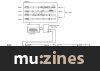
Circuit: See Figure 1. 5mA current loop type. Logical 0 is current ON. One output shall drive one and only one input. The receiver shall be optoisolated and require less than 5mA to turn on. Sharp PC-900 and HP 6N138 opto-isolators have been found acceptable. Other high-speed optoisolators may be satisfactory. Rise and fall times should be less than 2 microseconds.
Connectors: DIN five-pin (180°) female panel mount receptacle. An example is the Switchcraft 57GB5F. The connectors shall be labelled 'MIDI IN' and 'MIDI OUT'. Note that pins 1 and 3 are not used, and should be left unconnected in the receiver and transmitter.
Cables shall have a maximum length of 50 feet (15 metres), and shall be terminated on each end by a corresponding five-pin DIN male plug, such as the Switchcraft 05GM5M. The cable shall be a shielded twisted pair, with the shield connected to pin 2 at both ends.
A 'MIDI THRU' output may be provided if needed, which provides a direct copy of data coming in MIDI IN. For very long chain lengths (more than three instruments), higher-speed optoisolators must be used to avoid additive rise/fall time errors which affect pulse width duty cycle.
Notes on Channel Modes
Synthesisers contain sound generation elements called voices. Voice assignment is the algorithmic process of routing Note On/Off data from the keyboard to the voices so that the musical notes are correctly played with accurate timing.
When MIDI is implemented, the relationship between the 16 available MIDI channels and the synthesiser's voice assignment must be defined. Several Mode messages are available for this purpose. They are Omni (On/Off), Poly, and Mono. Poly and Mono are mutually exclusive, ie. Poly Select disables Mono, and vice versa. Omni, when on, enables the receiver to receive Voice messages in all Voice Channels without discrimination. When Omni is off, the receiver will accept Voice messages from only the selected Voice Channel(s). Mono, when on, restricts the assignment of Voices to just one voice per Voice Channel (Monophonic.) When Mono is off (=Poly On), any number of voices may be allocated by the Receiver's normal voice assignment algorithm (Polyphonic).
For a receiver assigned to Basic Channel "N," the four possible modes arising from the two Mode messages are:
| Mode | Omni | ||
|---|---|---|---|
| 1 | On | Poly | Voice messages are received from all Voice Channels and assigned to voices polyphonically. |
| 2 | On | Mono | Voice messages are received from all Voice Channels, and control only one voice, monophonically. |
| 3 | Off | Poly | Voice messages are received in Voice Channel N only, and are assigned to voices polyphonically. |
| 4 | Off | Mono | Voice messages are received in Voice Channels N thru N+M-1, and assigned monophonically to voices 1 thru M, respectively. The number of voices M is specified by the third byte of the Mono Mode Message. |
Four modes are applied to transmitter (also assigned to Basic Channel N). Transmitters with no channel selection capability will normally transmit on Basic Channel 1 (N=0).
| Mode | Omni | ||
|---|---|---|---|
| 1 | On | Poly | All voice messages are transmitted in Channel N. |
| 2 | On | Mono | Voice messages for one voice are sent in Channel N for step time. |
| 3 | Off | Poly | Voice messages for all voices are sent in Channel N for step time. |
| 4 | Off | Mono | Voice messages for voices 1 thru M are transmitted in Voice Channels N thru N + M-1, respectively. (Single voice per channel). |
A MIDI receiver or transmitter can operate under one and only one mode at a time. Usually the receiver and transmitter will be in the same mode. If a mode cannot be honoured by the receiver, it may ignore the message (and any subsequent data bytes), or it may switch to an alternate mode (usually Mode 1, Omni On/Poly).
Mode messages will be recognised by a receiver only when sent in the Basic Channel to which the receiver has been assigned, regardless of the current mode. Voice messages may be received in the Basic Channel and in other channels (all called Voice Channels), which are related specifically to the Basic Channel by the rules above, depending on which mode has been selected.
A MIDI receiver may be assigned to one or more Basic Channels by default or by user control. For example, an eight-voice synthesiser might be assigned to Basic Channel 1 on power-up. The user could then switch the instrument to be configured as two four-voice synthesisers, each assigned to its own Basic Channel. Separate Mode messages would then be sent to each four-voice synthesiser, just as if they were physically separate instruments.

(Click image for higher resolution version)
More with this topic
 MIDI - An Introduction |
 The Myths Of MIDI |
 General MIDI - A True MIDI Standard? |
 Inside MIDI |
 Adventures In MIDILand (Part 1) |
 MIDI In Control |
 Technically Speaking |
 Technically Speaking |
Introduction |
General MIDI - Who? What? Why? When? |
 BeeBMIDI Monitor (Part 1) |
Get Organised! - Keeping Track Of MIDI Connections |
Browse by Topic:
MIDI
Publisher: Electronics & Music Maker - Music Maker Publications (UK), Future Publishing.
The current copyright owner/s of this content may differ from the originally published copyright notice.
More details on copyright ownership...

Electronics & Music Maker - May 1984
MIDI Supplement - Part One
Feature
Help Support The Things You Love
mu:zines is the result of thousands of hours of effort, and will require many thousands more going forward to reach our goals of getting all this content online.
If you value this resource, you can support this project - it really helps!
Donations for June 2026
Issues donated this month: 0
New issues that have been donated or scanned for us this month.
Funds donated this month: £0.00
All donations and support are gratefully appreciated - thank you.
Magazines Needed - Can You Help?
Do you have any of these magazine issues?
If so, and you can donate, lend or scan them to help complete our archive, please get in touch via the Contribute page - thanks!