


Magazine Archive
Home -> Magazines -> Issues -> Articles in this issue -> View
Workbench (Part 2) | |
Group Lighting BoardArticle from International Musician & Recording World, November 1985 | |
Phil 'DIYse up' Walsh sheds yet more light on your band
You should now be in the position of having working power supply and chaser boards and so we can start thinking about mounting them in a suitable case. If your eventual goal is a rope light controller or an LED chaser then a plastic box will do but the mains lamp controllers will need a metal case as some of the components use the case as a heatsink. For ease of construction I would recommend a fairly large case as it makes life simpler if you aren't trying to cram quarts into pint pots. As a guide the plastic case could be black ABS, 140x90x55mm, and the metal one an aluminium box 203x150x75mm. Despite the odd dimensions (or maybe because of them) those are standard size cases and are widely available from electronic component shops.
In order that you can plan out your box I give below approximate dimensions of all the boards — it's worth remembering that some of the boards can be mounted vertically on the sides of the box should you wish.
| Chaser board | 90x45mm |
| Strobing/Dark space board (mains) | 50 x 50mm |
| LED Interface board | 65x65mm |
| Mains lamp Interface board | 75x40mm |
| Rope light Interface board | 60x60mm |
Remote Switching
There are a few optional extras such as remote footswitch control, offering blackout and chase override (all lamps on) options. If you are tempted by these then it's worth doing the necessary mods to the chaser board now.
Remote Switching
1. Cut link A10-E10 near to the A rail and re-solder the link into D10 (link now runs from D10 to E10).
2. Cut out and remove the A16-H16 link.
3. Cut the Veroboard track at location A18.
4. Solder a link between A30 and D30.
5. Solder a link between H21 and D21.
6. Solder two longish lengths of wire, one to A12 and the other to A31.
7. Solder a longish length of wire to location N6.
Installing the transformer and chaser board
Before fixing these in place you should solder a few more wires to the chaser board.
1. Solder three longish lengths of wire to locations N7, N8 and N9.
2. If you are building the LED chaser, solder a longish length of wire to A32.
The transformer and chaser board can now be fixed into the chase, noting the following:-
1. The LED chaser and rope lights will run satisfactorily using three amp mains cable, but if you are driving stage lighting you must use heavy duty, 13 amp cable.
2. The mains lead should be brought into the case through a rubber or plastic grommet and should be anchored to provide some sort of strain relief.

FIG 1. MAINS LEAD AND TRANSFORMER DETAILS
3. Connect the mains cable into a three way terminal block (use a 15amp block if running stage lighting, if not a two or five amp will do). See Figure one.
4. For all options except the LED chaser, connect the wire from N7 into the neutral (blue cable) side of the terminal block as shown in Figure one.
N.B. It is essential that the mains plug is correctly wired (see Figure two) or the circuit may be damaged.
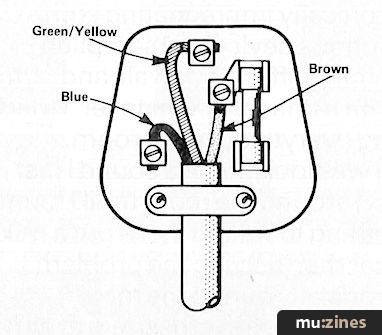
FIG 2. MAINS PLUG WIRING
5. Using 6BA nuts and bolts and a suitable drill fix the chaser board to the case by drilling three holes in the Veroboard at locations P4, P30 and B23. To ensure that the fixing bolts cannot possibly short circuit the board it is sensible to cut the board tracks at A25, B25, C25, A20, B20 and C20.
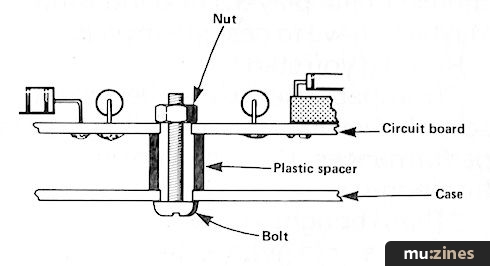
FIG 3. FIXING THE BOARD TO THE CASE
6. Cut three, 1cm lengths of plastic tubing from an old felt tip pen case and, using these as spacers, bolt the board to the case, (see Figure three)
7. Drill a hole for the potentiometer. Sometimes they have an antirotation spigot which stops them seating flat; if so snap it off with a pair of pliers. Tighten the pot into place and cut the pot shaft to about 1 cm using a hacksaw.
8.a If you have wired the board for the On/Off switch option, mount a second three way terminal block (two or five amp) in the case.
b In a suitable box mount two DPDT footswitches, two LEDS and two 1K ohm resistors as shown in Figure four.

FIG 4. REMOTE CONTROL FOOTSWITCH DETAILS
c Use four core cable to connect up as shown in Figure four. If you have difficulty finding four core cable then try twin stereo cable (the type that has two insulated screens and cores running side by side) or tape together two lengths of twin bell wire.
The wiring is arranged so that the LEDs glow when:
The lights are all off (On/Off LED)
The lights are chasing (All/Chase LED)
If you think about it for a minute this makes sense because on a pitch dark stage the On/Off LED will lead your foot to the switch that will switch on the lights so you can see the footswitch.
At this point there is a terminal on the block which is not connected — fear not, that wire comes from a board yet to be built.
Strobing/Dark Space board
This board allows you three choices for the way your mains lamps, LED or rope light bulbs flash. The choices are:-
1. Standard sequencing, ie A—B—C—D—A—B— etc. On a rope light this gives the familiar 'lights chasing along a rope'.
2. Dark Space sequencing. In this mode three lamps out of four are on at any one time and the lamp being off (the dark space) is what sequences. On a rope light this gives the effect of a dark patch moving along an illuminated rope. With stage lights it offers a higher level of stage illumination than choice one whilst giving a pleasing flashing light effect.
3. Strobing. All the lamps flash on and off together.
With all these choices the chaser board speed control offers a wide range of speeds.
Parts List
12 off 1N4148 diode
4 off 1M ohm ⅛ watt resistor
1 off 4 pole, 3 way rotary switch
1 off Veroboard 0.1" pitch at least 2"x2"
4 off 6BA nuts and bolts and plastic spacers
Insulated hook up wire, preferably 4 different colours

FIG 5. VEROBOARD LAYOUT FOR MAINS STROBING/DARK SPACE BOARD
Construction
This should be fairly straightforward. There are no track cuts in the Veroboard. All the diodes face the same way, so with a little care there should be few problems (see Figure five). Make sure you solder the diodes fairly quickly and blow them cold after each joint as they can be damaged if they get too hot. The five wires from the chaser board and the eight wires to the switch should then be soldered into place. The three groups of four wires represent the four channels so colour coding the wires would be helpful, eg the wire from chaser board G2, the wire to switch terminal one and the wire to switch terminal two are all related to channel A etc.
The switch wiring can be a little tricky so some care is called for. Carefully bend the 12 tags around the edge of the switch outwards to give yourself a little room to work in.
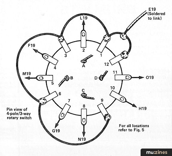
FIG 6. SWITCH WIRING DETAILS SHOWING CONNECTIONS FROM STROBING/DARK SPACE BOARD
Firstly link tags 1, 3, 6, 9 and 12 as shown in Figure six. Solder four lengths of (colour coded) wire to centre tags A, B, C and D. Referring to Figs five and six, solder the eight wires from the Strobing/Dark Space board to the appropriate tags.
Finally, bolt the board into the case using similar techniques as for the chaser board and mount the rotary switch in a suitable place in the case. When removing the nut and star washer from the switch prior to fixing be sure not to disturb the flat washer with its locking spigot — this sets the operation of the switch to three clicks.
Testing
Should you wish to test the work so far then proceed as follows:-
Connect an LED with a 1K ohm resistor in series between the negative rail (eg wire N9 from the chaser board) and each of the switch outputs A, B, C and D in turn, making sure that the flat on the LED case is nearest the negative rail. (See Figure seven).
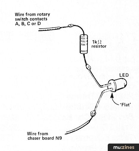
FIG 7. TESTING THE STROBING/DARK SPACE BOARD & ROTARY SWITCH
The LED should flash once in every four counts with the switch in the clockwise or anticlockwise positions and should stay on but flash off at the same rate with the switch in the central position. If fitted the On/Off footswitch can also be tested. Although the All/Chase switch should operate its indicator light, it will not affect the circuit yet.
Next month: Rope light, Mains (Stage) lamp and LED interface boards.
Series - "Group Lighting Board"
All parts in this series:
This is the only part of this series active so far.
More with this topic
 The Electric Drummer (Part 1) |
 Short Circuit |
 BeeBMIDI (Part 1) |
 The Ultimate Blinky Light - LED Wall Art - Visual Environment Machine |
 Voltage-Controlled Clock for Analogue Sequencers |
 Workbench - Sounding Out |
 Adding an Independent Tracking Output to the 4780 Sequencer |
 Technically Speaking |
 Digisound Voice Card (Part 1) |
 Technically Speaking (Part 1) |
 Voice Frequency to Voltage Converter |
 Workbench - CHECKA |
Browse by Topic:
Electronics / Build
Publisher: International Musician & Recording World - Cover Publications Ltd, Northern & Shell Ltd.
The current copyright owner/s of this content may differ from the originally published copyright notice.
More details on copyright ownership...

International Musician - Nov 1985
Donated by: Neill Jongman
Topic:
Electronics / Build
Series:
Group Lighting Board
This is the only part of this series active so far.
Feature by Phil Walsh
Previous article in this issue:
Next article in this issue:
Help Support The Things You Love
mu:zines is the result of thousands of hours of effort, and will require many thousands more going forward to reach our goals of getting all this content online.
If you value this resource, you can support this project - it really helps!
Donations for May 2026
Issues donated this month: 0
New issues that have been donated or scanned for us this month.
Funds donated this month: £0.00
All donations and support are gratefully appreciated - thank you.
Magazines Needed - Can You Help?
Do you have any of these magazine issues?
If so, and you can donate, lend or scan them to help complete our archive, please get in touch via the Contribute page - thanks!