Magazine Archive
Home -> Magazines -> Issues -> Articles in this issue -> View
ZX81 Sequencer | |
Article from Electronic Soundmaker & Computer Music, January 1984 | |
100 notes on a budget
Presenting the world's cheapest computer sequencer, designed by Peter Rodgers
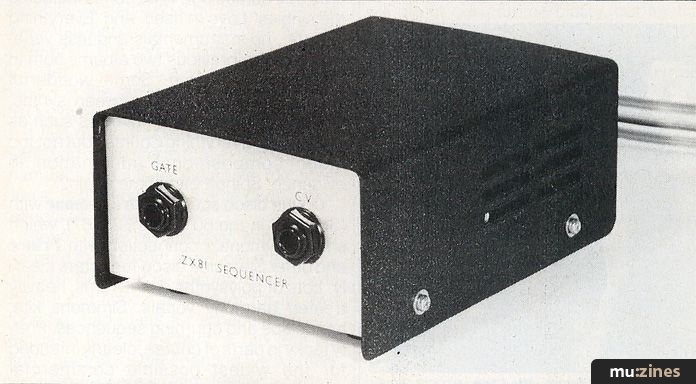
There are those who take the view that the Z80A microprocessor can be used in a multitude of useful applications, or it can be used in a Sinclair ZX81 home-computer. But this cynical attitude overlooks the great potential that the ZX81 has for use in control applications. With its cassette interface, television output, keyboard, BASIC interpreter, useful amount of memory (for control applications), and expansion port the ZX81 with a suitable interface, represents about the least expensive way of entering the world of micro-controllers.
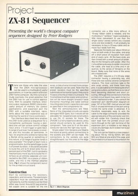
The interface described here enables the ZX81 to be used as a sequencer for a monophonic synthesizer having a standard one volt per octave control voltage input, and a +5 volt trigger or gate input. A range of just over five octaves is covered, and this includes all semitones. In fact, for anyone who wishes to transcribe a Bartok string quartet or something of this nature, a full range of quarter tones is also available! The length of each note is programmable, but the gate/trigger pulse is of preset duration. It would be possible to build the unit to fit direct onto the expansion port of the ZX81, but it is probably mechanically more sound to build the interface as an entirely separate unit connected to the ZX81 via a piece of ribbon cable, and this is the method adopted here. Fig 4 shows the component layout for the printed circuit board.
Construction
Start by connecting the resistors, capacitors, and link wires. The electrolytic capacitors must be connected with the right polarity, but the resistors can be fitted either way round. Around 22 swg enamelled copper wire is suitable for the link wires, or bits of wire trimmed from component leadouts can be used. Note that the preset resistors must be the specified subminiature horizontal types if they are to fit easily onto the printed circuit board. The finished board will be neater and construction will be more straight forward if axial (horizontal mounting) and radial (vertical mounting) electrolytic capacitors are used as specified in the components list.
Next the semiconductors are fitted. None of the integrated circuits are easily damaged MOS types, but it would still be advisable for inexperienced constructors to use DIL IC sockets for these. The ZN428E is a fairly expensive device, and a socket should certainly be used for this component. Take care to fit all the semiconductor devices the right way round.
Single-sided 1 mm Veropins are fitted to the board at points where connections to the sockets and ZX81 will be made. The connections to the sockets are quite straightforward, but the ones to the edge connector are a little more difficult. A 16-way ribbon cable is needed, and the multicolour ("rainbow") type is probably a little more convenient to use than the single colour variety (where any crossed wires are less evident). It will probably be necessary to buy a 20-way cable and remove four leads from this.
Separate the leads over about 25mm or more at both ends of the cable, and strip off a short piece of insulation from each end of every wire. All the bare ends are then tinned with a small amount of solder. Also tin the Veropins with solder. After this it should be quite easy to solder one end of the cable, one lead at a time and in sequence, to the series of Veropins on the board. Make sure that none of the wires are crossed over.
The ZX81 requires a 2 X 23-way edge connector having a polarising key, and these are now sold by several component retailers. The most common type is the wire wrap variety, and these have long pins. It is advisable to trim these quite short using wire cutters, so that there is no risk of them becoming distorted and short circuiting. Although the connections from the printed circuit board may seem to be in a rather haphazard order, if you consult the expansion port identification diagram on page 167 of the ZX81 manual you will see that (if unused terminals of the port are ignored) the same order is obtained. It is therefore reasonably easy to wire the cable to the edge connector provided the appropriate pins of the connector are tinned with solder first. Carefully check that each lead from the printed circuit connects through to the right terminal of the expansion port; a mistake is not likely to cause any damage, but it is best not to put this to the test.
The unit can be fitted in a case measuring about 150 by 100 by 50mm. SK1 and SK2 are fitted at one end of the case, and the printed circuit board is mounted on the base panel using M3 or 6BA fixings. If the case is a metal type, use spacers around 6 to 12mm over the mounting bolts to prevent the connections on the underside of the board from touching the case and short circuiting through it. With most cases it will be possible to take the ribbon cable through the small gap that is usually present between the chassis and the outer casing, but if necessary a suitable cutout for the cable must be filed in the case.
Adjustment
Connect the sequencer interface to the ZX81 before connecting power to the latter. When switched on, the ZX81 should behave quite normally with the "K" cursor appearing in the bottom left hand corner of the screen. Switch off at once and thoroughly recheck the interface if it does not.
With the CV output of the interface connected to the CV input of the synthesizer using a normal jack lead, the command POKE 9000, two is typed into the ZX81. By pressing a key or using the 'Drone' switch to give an output from the synthesizer, VR1 is adjusted to give a note which is identical to the one obtained from the lowest key of the keyboard. Next the command POKE 9000,50 is typed into the ZX81, and VR2 is adjusted for an output note exactly two octaves higher than the original note. Then type POKE 9000, two again, and repeat this procedure until no further adjustment of VR1 and VR2 is required. The notes of the keyboard then correspond to even numbers POKEd to address 9000 (or any address in the range specified earlier). Odd numbers give quarter tones (which are useful for quasi-glissando effects if nothing else). As only seven lines of the data bus are fed to the D/A converter, 127 is the highest number that can be used, and this gives a range of just over five octaves. Even if the keyboard only gives a range of around two or three octaves, using the sequencer it will almost certainly be possible to obtain the full five-and-a-bit octave range.
VR3 controls the length of the gate/trigger pulse from SK2, and it will normally be necessary to set this almost fully anticlockwise so that a short pulse duration is produced. Remember that the pulse length should not be longer than the duration of the shortest note, or some odd sounding results may be obtained. VR3 could be replaced with an 470k linear potentiometer mounted on the front panel if preferred.
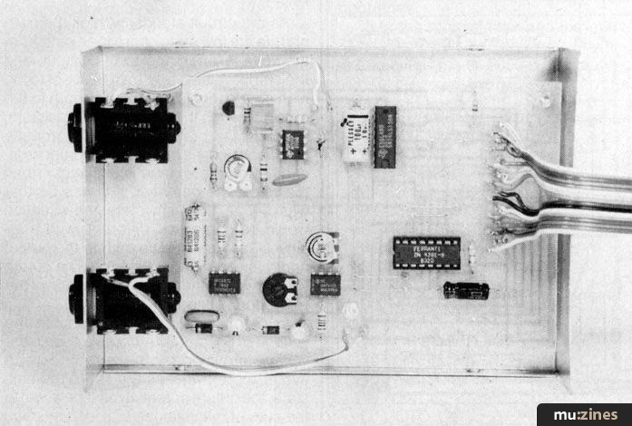
Inside the ZX81 Sequencer
Software
The basic way of producing a sequence is to POKE the appropriate numbers to address 9000, using the PAUSE function after each note to set the note length. The number following the PAUSE command gives the note duration in fiftieths of a second, and provides a more than adequate degree of control.
There are more elegant ways of doing things than using a series of POKEs and PAUSES. The first suggested programme plays a loop, starting as soon as the last time is entered. The number of notes in the loop is entered at the beginning of the programme, and around 45-50 notes can be entered. Note and time numbers are entered as requested by the programme. Escape by pressing "BREAK" only.
When the larger programme is run, pressing "I" allows notes to be entered. You must enter the number of the note (its position in the sequence), the pitch number, and duration, according to the screen prompts. Notes can be entered in any order, but must fill consecutive elements in the array starting at one. The programme will regard any empty element as the end of the sequence. Entering 0 as the note number ends the entry procedure and the sequence can then be played by pressing "P". Pressing any key stops the play loop. It is then possible to alter or extend the sequence by pressing "I", or to save the sequence and programme by pressing "S". Start the tape before pressing this key.
This programme uses a string array together with CODE and CHRS to save the values, which enables more notes to be achieved than could be accommodated with a numeric array. Note that there must always be one element at the end of the note sequence left empty (ie, at 0), or the programme will stop after playing the sequence once, giving an error message. Up to 99 notes (not including the empty element) can be entered.
Figure 1 shows the general arrangement of the ZX81 sequencer in block diagram form.
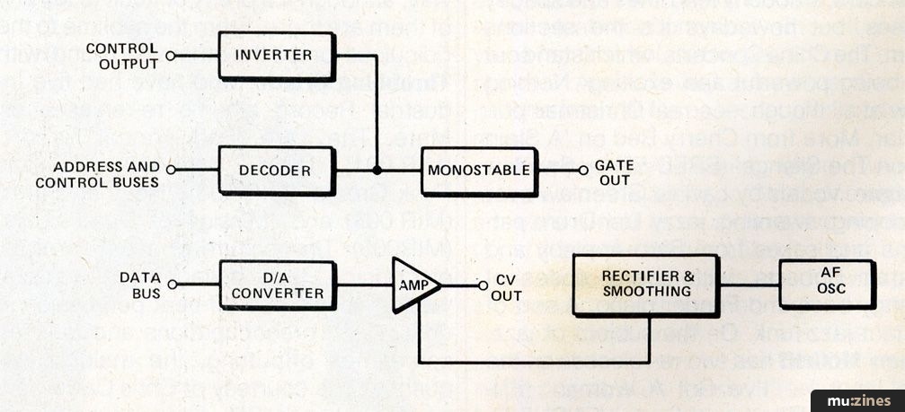
Fig 1 — Block Diagram.
The digital to analogue (D/A) converter is at the heart of the unit, and this takes an eight bit binary number from the data bus of the computer and converts it into a corresponding voltage. The basic idea is that the computer places a series of numbers onto the data bus at the appropriate intervals, and the D/A converter changes these into voltages which produce the required notes when fed to the CV input of the synthesizer.
The series of voltages generated by the D/A converter go up in equal increments of approximately 0.1 volts. This is similar to the series of voltages produced by the keyboard of a synthesizer, which also gives a set of voltages having equal increments between one level and the next. However, the size of the increment is larger for the keyboard, and an amplifier is therefore used at the output of the D/A converter to give the appropriate voltage step.
In order to give an output voltage range that can swing right down to zero volts, the amplifier requires a negative supply in addition to the 0V and positive supply rails. As the ZX81 does not provide a negative supply output a suitable potential is generated from the positive supply rail using an audio oscillator feeding into a rectifier and smoothing circuit. This is a very convenient method as it enables the interface to be fully powered from the ZX81 power pack, and no additional mains power supplies are needed.
Apart from the required numbers which correspond to the note sequence, there are a great many other numbers that appear on the data bus of the ZX81 as part of its normal operation. The circuit has to incorporate some means of differentiating between the numbers of the note sequence and the other numbers on the data bus. This is the purpose of the decoder circuit, which monitors the logic levels on some of the address and control lines of the ZX81. These produce a certain combination of logic levels only when data for the D/A converter is present on the data bus, and the decoder only produces an output pulse while this set of states is present.
This pulse is fed to the transparent latch at the input of the D/A converter. During the control pulse the latch allows the signal on the data bus to go through to the input of the D/A converter, but when the pulse finishes the output of the latch remains static until the next pulse is received. In other words, each time a control pulse is received the new number on the data bus is supplied to the D/A converter, and this number is held in the latch and continues to be fed to the D/A converter until a new number and control pulse are received. This latching action is essential because the sequencer must provide a continuous output to the CV input of the synthesizer. It is no good just providing a brief output during the periods that the required numbers are present on the data bus.
A gate or trigger pulse for the synthesizer will normally be required, and the output pulse from the decoder may seem an obvious way of obtaining a suitable signal. However, this pulse is of the wrong polarity and is far too short in duration to activate most synthesizers. A monostable multivibrator is used as a pulse stretcher, and also to provide an inverting action, so that a gate/trigger pulse having suitable characteristics is produced.
Due to its limited amount of built-in memory the ZX81 does not need to fully decode its address bus, and does not actually do so. As a result of this the read only memory (ROM) which contains the BASIC interpreter occupies several blocks of memory space, and not just one. The sequencer is placed in the ZX81 memory map at a position occupied by one of the so called "ROM echoes", and the ROM therefore has to be switched off while fresh data is being sent to the sequencer, but the ROM must be allowed to function normally at other times. The output of the decoder is inverted and applied to the appropriate control terminal of the ZX81's control bus so that the ROM is disabled at the appropriate times.
D/A Converter
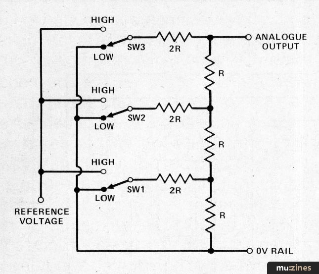
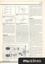
Fig 2a — The arrangement used in the D/A converter.
The digital to analogue converter used in this design is based on the ZN428E integrated circuit. This uses the standard arrangements shown in Fig 2(a), which is a precision voltage stabiliser feeding a network of electronic switches which in turn feeds a 2R-R precision resistor network. Each switch is controlled by one of the lines of the data bus, and is high if its input is at the high logic state, or low if it is at the low state.
As the circuit stands, with all the switches in the low state, there is no path from the voltage reference to the output, and the output voltage is zero. If S3 is set to the high state there is a fairly easy path to the output through the first of the 2R resistors, although the other resistors do produce significant losses through this component, and the output voltage is a little over half the reference potential. If it was S1 that was set to the high state the situation would be somewhat different, with a relatively high resistance path to the output and a lower shunt resistance. The output voltage would then only be a fraction of the reference voltage.
In practice S2 must give double the voltage of S1, and S3 must give double the voltage provided by S2. Furthermore, if two or more switches are set to the high state, the output potential must be equal to the sum of the voltages provided by each switch. This arrangement does in fact meet both requirements, but you will need to do a lot of arithmetic if you wish to prove this for yourself! Although only three switches and 2R—R resistor stages are shown in Fig 2(a), this arrangement can be extended to have any desired number of switches and resistor stages, and it will always function in the required manner.

Fig 2b — The arrangement used in the Output Amplifier.
An operational amplifier (op amp) is employed in the output amplifier which uses the arrangement of Fig 2(b). The gain from the non-inverting (+) input of the device to its output is determined by the two resistor network (Ra-Rb) which provides negative feedback from the output to the inverting (-) input. The voltage gain is equal to the sum of Ra and Rb divided by Rb. Therefore, the higher the value of preset resistor Ra, the higher the gain of circuit. Ra can thus be adjusted to set the voltage gain of the circuit at the correct level.
In theory the minimum output voltage of the D/A converter should be zero, and this should give an output of zero volts from the amplifier. In reality there are small errors known as 'offset voltages' that occur, and offset null control Rc is used to trim these out so that accurate results are obtained with low output voltages.
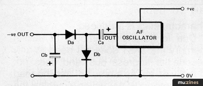
Fig 2c — The method of deriving the negative supply rail.
The negative supply for the operational amplifier is generated using the arrangement shown in Fig 2(c). The audio oscillator is a straight forward C—R type based on a 555 timer IC. This device is a good choice for this application since it has an output stage which can provide plenty of output current, and it is therefore quite capable of providing the few milliamps of supply current required by the operational amplifier. Ca couples the output of the oscillator to the rectifier circuit which is comprised of Da and Db in a conventional configuration. The polarity of the output voltage depends on which way round the two diodes are connected, and in this case they are obviously connected to give negative output pulses. Cb is used to smooth these to produce a reasonably ripple free negative DC output. The output voltage is not quite equal to the input supply potential due to losses through the diodes and the output stage of the oscillator, but this set-up is efficient enough to give a more than adequate supply potential for this application.
The decoder is a single logic device which gives the required negative output when the input lines are. at the correct logic states. The monostable circuit is almost as simple, and it uses a 555 which is triggered direct from the output of the decoder. Apart from the 555 only a simple C-R network (which sets the output pulse length) is used.
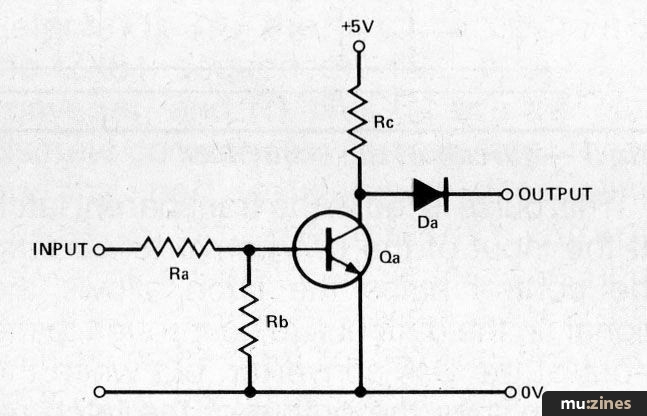
Fig 2d — The configuration used in the Inverter stage.
The inverter stage uses the configuration shown in Fig 2(d). The input is normally high so that Tra is switched hard on and the output is low. When the output of the decoder pulses low Tra is switched off, and the output pulses high. This signal is coupled by Da to the appropriate input (ROMCS) of the ZX81 expansion port.
It is important that the inverter should not force the ROMCS line low when its output is in the low state, but should instead leave internal circuits of the ZX81 to control this line. This is the reason for including Da in series with the output. It enables Rc to pull the output high, but it blocks a current flow in the opposite direction so that Tra switching on does not prevent a circuit within the ZX81 from pulling the output to either logic level.
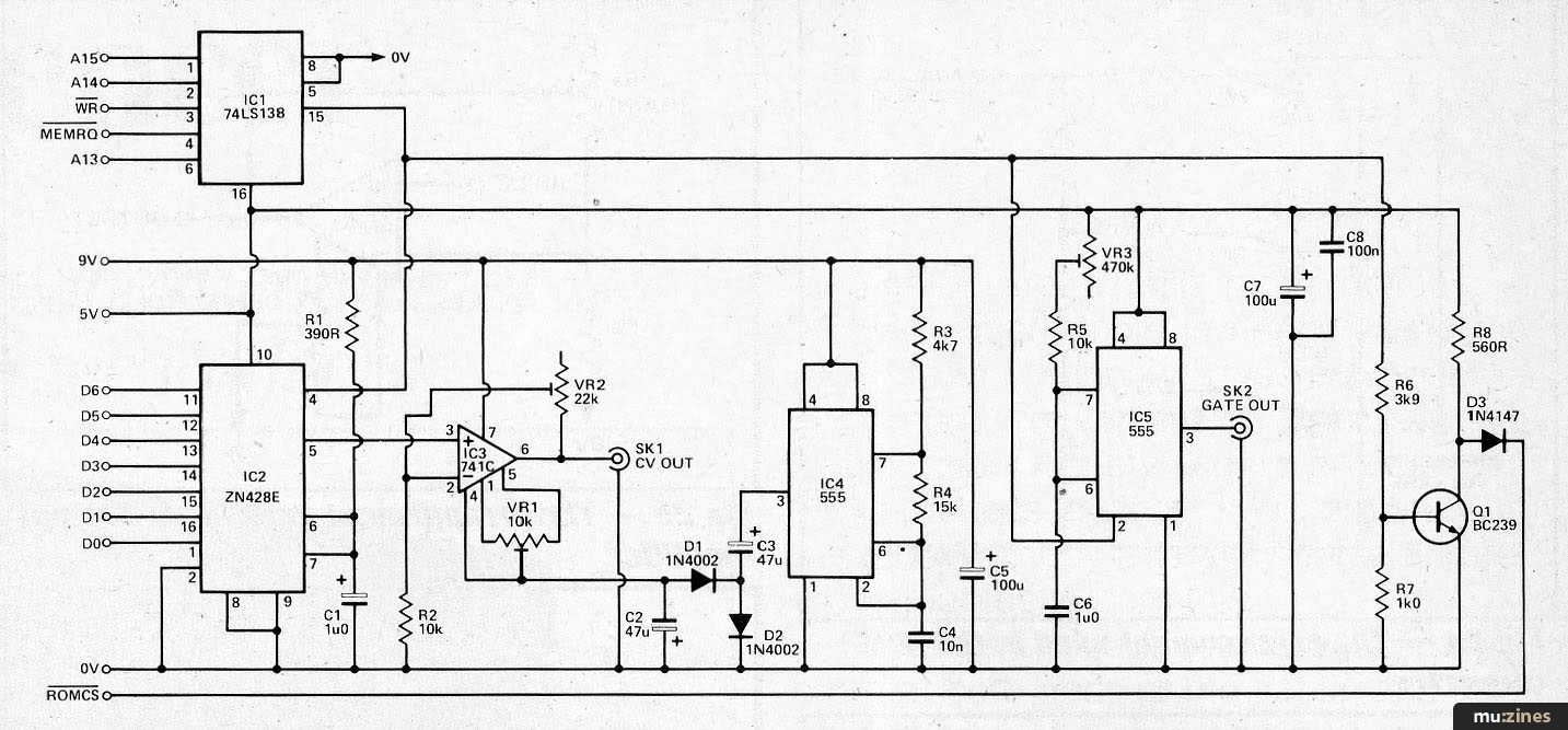
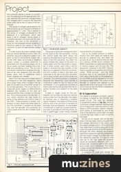
Fig 3 — Circuit of the sequencer
(Click image for higher resolution version)
The Circuit
Refer to Fig 3 for the full circuit diagram of the ZX81 sequencer. IC2 is the D/A converter, and R1 plus C1 are the only discrete components this requires. These are the load resistor and decoupling capacitor for the internal voltage reference generator. Note that one input of IC2 is wired to the 0 volt rail, and that only seven of the eight are fed from the ZX81 data bus. This gives 128 different output levels (including zero volts), and a range of just over five octaves including semi and quarter tones.
IC3 is the output amplifier, and this boosts the output of the D/A converter by a factor of just over two times. IC4 is the audio oscillator, and the timing components (R3, R4, and C4) have been given values that give oscillation at a high audio frequency of several kilohertz. This enables reasonably low values to be used for C3 and C4.
IC1 is the decoder integrated circuit, and this is a three to eight line decoder. The three inputs are used to decode the A15, A14, and WR (write) line of the ZX81. These are all low when the computer writes to the D/A converter, and the negative output pulse is obtained from output 0 at pin 15. Two of the enable inputs of IC1 are used to decode the MEMRQ (low) and A13 (high) lines. As the address bus is only partially decoded the sequencer interface appears at a wide range of memory addresses — all addresses from 8192 to 16383 in fact, but this is of little practical importance.
IC5 is the monostable, and the output pulse length can be preset at anything from about 11ms to 500ms by means of VR3. Tr1 is used as the basis of the inverter stage.

Fig 4 — PCB and component layout
(Click image for higher resolution version)

The foil pattern for the ZX81 sequencer
(Click image for higher resolution version)
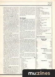
20 INPUTN
30 DIM S(N,2)
40 FOR C = 1 TO N
50 CLS
60 PRINT C
70 PRINT "NOTE"
80 IN PUT S(C,1)
90 PRINT "TIME"
100 INPUT S(C,2)
110 NEXT C
120 FOR C = 1 TON
130 POKE 9000, S(C,1)
140 PAUSE S(C,2)
150 NEXT C
160 GOTO 120
20 PRINT "I = INPUT: P = PLAY: S = SAVE"
30 PAUSE 32767
40 LET K$ = INKEY$
50 IF K$ = "I" THEN GOSUB 100
60 IF K$ = "P" THEN GOSUB' 200
70 IF K$ = "S" THEN SAVE "TUNE"
80 CLS
90 GOTO 20
100 CLS
105 PRINT "NOTE NO? (0 TO EXIT)"
110 INPUT N
115 IF N=0 THEN RETURN
120 PRINT "PITCH?"
130 INPUTS
135 LET S$(N,1) = CHR$(S)
140 PRINT "TIME?"
150 INPUTS
155 LET S$(N,2) = CHR$(S)
160 GOTO 100
200 CLS
210 PRINT "PRESS ANY KEY TO STOP"
220 LET N = 1
230 IF CODE S(N,1) = 0 THEN GOTO
240 POKE 9000, CODE S$(N,1)
250 PAUSE CODE S$(N,2)
260 LET N = N + 1
270 IF INKEY$ "''THEN RETURN
280 GOTO 230
Parts List
| Resistors | |
| R1 | 390R |
| R2,5 | 10k |
| R3 | 4k7 |
| R4 | 15k |
| R6 | 3k9 |
| R7 | 1k |
| R8 | 560R |
Potentiometers | |
| VR1 | 10k 0.1W horiz. preset |
| VR2 | 22k 0.1W horiz. preset |
| VR3 | 470k 0.1W horz. preset |
Capacitors | |
| C1 | 1u 63V axial elect |
| C2,3 | 47u 10V radial elect |
| C4 | 10n polyester |
| C5,7 | 100u 10Vaxial elect |
| C6 | 1u carbonate |
| C8 | 100n ceramic |
Semiconductors | |
| IC1 | 74LS138 |
| IC2 | ZN428E |
| IC3 | 741C |
| IC4,5 | 555 |
| Q1 | BC239 |
| D1,2 | 1N4002 |
| D3 | 1N4148 |
Miscellaneous | |
| SK1,2 | Standard 6.35mm jack sockets |
| 2 X 23-way ZX81 type edge connector, Case about 150 x 100 x 50mm, Printed circuit board, Veropins, ribbon cable, etc. | |
More with this topic
The Spectrum Synthesiser (Part 1) |
Voltage-Controlled Clock for Analogue Sequencers |
Experimenters Circuits - Using The CA3080 |
Voltage Controlled Clock |
The Ins and Outs of Digital Design |
Augmenting the 3750's Memory |
Workbench - Go Active! |
Spotlight - Early Experiments with Computer Music |
Workbench - Remote Control System |
Adventures with Op-Amps |
Lab Notes: The Polyphonic Synthesizer |
De-Esser Project |
Browse by Topic:
Electronics / Build
Publisher: Electronic Soundmaker & Computer Music - Cover Publications Ltd, Northern & Shell Ltd.
The current copyright owner/s of this content may differ from the originally published copyright notice.
More details on copyright ownership...
Feature by Peter Rodgers
Help Support The Things You Love
mu:zines is the result of thousands of hours of effort, and will require many thousands more going forward to reach our goals of getting all this content online.
If you value this resource, you can support this project - it really helps!
Donations for November 2025
Issues donated this month: 0
New issues that have been donated or scanned for us this month.
Funds donated this month: £0.00
All donations and support are gratefully appreciated - thank you.
Magazines Needed - Can You Help?
Do you have any of these magazine issues?
If so, and you can donate, lend or scan them to help complete our archive, please get in touch via the Contribute page - thanks!

