


Magazine Archive
Home -> Magazines -> Issues -> Articles in this issue -> View
Parametric Equalizer | |
Article from Electronic Soundmaker & Computer Music, September 1983 | |
Single channel design
A single channel, modular equalizer with variable centre frequency. Design by Keith Simon.

A parametric equalizer has a wide range of uses. However, the design presented here should appeal to musicians that would like to 'individualise' the sound of their instruments and tapes.
The equalizer features three controls; the first sets the frequency at which equalization is performed (infinitely variable between about 150Hz and 1600Hz), while the second determines the amount of boost (or cut) the selected frequency band will receive. The last control governs the range of frequencies on either side of the centre frequency on which the unit will have an effect. This last control is referred to as the Q pot (the effect of varying the Q is shown in Fig 1).

Figure 1. The difference between low Q and high Q responses
Circuit Outline
The circuit can be split into three distinct sections — two of which are very similar. In order that the circuit operation will not alter if it is used with different items of equipment, it is necessary to 'isolate' the filter from the effects of any variations in the input impedance 'seen' by the equaliser, by providing an input buffer amplifier. For similar reasons the output of the equaliser is buffered by a similar amplifier.
Buffers

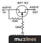
Figure 2. Circuit of a basic amplifier
Both buffer amplifiers are formed by low noise amplifiers. Fig. 2 shows just how straightforward the stages are. The amplifiers are configured as unity gain, inverting types and their characteristics are completely governed by just two resistors.
In operation, a positive signal at the input will cause an exact copy of the signal to appear at the amplifiers output but, as the amplifier is inverting, it will be in the negative direction. A small part of this negative output signal will find its way back to the input via Rb of Fig. 2. This will tend to oppose the input signal that started the chain of events. Rb is known as the feedback resistor and the higher its value, the less the signal fed back will be and the higher the gain of the stage will become. A lower Rb will, in a similar fashion, decrease the amplifier's gain.
In the case of the parametric equaliser, resistors have an equal value and the gain of the amplifier is one. If it seems pointless to have an amplifier with a gain of unity, remember the purpose of this stage of the equaliser is, in fact, not to amplify, but to provide isolation between the unit and any external equipment it is to be used with.
Filters
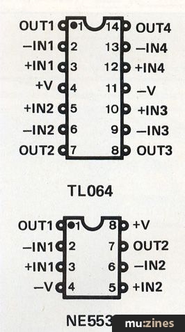
Figure 3. Pin connections on the TL064 and ME5532
The heart of the equaliser is formed by the four operational amplifiers in the quad op-amp package. The section around IC2a is a familiar inverting op-amp stage, this time with a gain of about two.
Operation of the other three amplifiers is quite complex and would require a page of formulas and a BSc in Applied Maths to get through. Very basically though, two of the stages, IC2c and IC2d can be recognised as being similar to the standard inverting op-amp stage but with a capacitor replacing the feedback resistor. Since capacitors change their 'resistance' as frequency changes, it's a fair assumption that the gain of the amp would depend on the input frequency. The ganged frequency pot replaces Ra and determines the amount of amplification.
IC2b is again a straightforward amplifier, but both its inverting and non-inverting inputs are used. In this case the amplifier acts as a summing stage. The Q control varies the characteristic of IC2b to provide the variable bandwidth function.
The op-amps require both positive and negative supplies and these are best provided by two 9V batteries.
Construction
The building of any project is greatly simplified if a PCB is used. Following the pattern shown, it is only necessary to place all the components in the correct position to build the unit.
Take care that the ICs and electronic capacitors are fitted the right way round — it is a good idea to use sockets for the ICs in case of any problems, as it is very difficult to remove an 1C once it's soldered into place.
When the board is complete it can be fitted into a case along with the batteries and suitable input/output sockets.
In Use
To test the unit, connect up a suitable input signal — music with a wide frequency content is OK — and, with the Q control set to minimum and the other pots set to their centre position turn the unit on. Gradually turn the level control towards the boost position. It should be possible to note the effect on the input signal.

Figure 4. Schematic of the Parametric Equaliser
(Click image for higher resolution version)

The prototype before being boxed. The number of units built will determine the case used

Figure 5. PCB pattern
(Click image for higher resolution version)

Figure 6. Component overlay
(Click image for higher resolution version)
Parts List
| Resistors | |
| R1,2,4,5,7,8,9,11,13,14 | 10k |
| R3 | 680R |
| R6,10 | 4k7 |
| R12 | 2k2 |
| R15 | 220R |
Potentiometers | |
| VR1 | 100k dual gang linear |
| VR2 | 10k linear |
| VR3 | 100k linear |
Capacitors | |
| C1,2,3,4 | 100n polyester |
| C5 | 220u 25V elect |
Semiconductors | |
| IC1 | NE5532 |
| IC2 | TL064 |
Miscellaneous | |
| PCB, Case, On/Off Switch, Wire etc. | |
More with this topic
 Magic Buttons - Touch Switch Theory |
 Experimenters Circuits - Using The CA3080 |
 Workbench |
 The Programmable Digital Sound Generator (Part 1) |
 How to Calm Hysterics in Op-amps |
 Studio Earthing Techniques - Interconnect (Part 1) |
 Building A Bionic Sax |
The Transpozer (Part 1) |
 Electro-Music Engineer - Transistor Power Amplifier Surgery |
 Equally Tempered Digital to Analog Converter |
 Workbench - Go Active! |
 Lab Notes: Computer Music Without the Computer - or: What to do 'til your processor arrives. |
Browse by Topic:
Electronics / Build
Publisher: Electronic Soundmaker & Computer Music - Cover Publications Ltd, Northern & Shell Ltd.
The current copyright owner/s of this content may differ from the originally published copyright notice.
More details on copyright ownership...

Electronic Soundmaker - Sep 1983
Donated & scanned by: Mike Gorman
Feature by Keith Simon
Previous article in this issue:
Next article in this issue:
Help Support The Things You Love
mu:zines is the result of thousands of hours of effort, and will require many thousands more going forward to reach our goals of getting all this content online.
If you value this resource, you can support this project - it really helps!
Donations for June 2026
Issues donated this month: 0
New issues that have been donated or scanned for us this month.
Funds donated this month: £0.00
All donations and support are gratefully appreciated - thank you.
Magazines Needed - Can You Help?
Do you have any of these magazine issues?
If so, and you can donate, lend or scan them to help complete our archive, please get in touch via the Contribute page - thanks!